
Centrifugal vibrating rod easy to control

A vibrating rod and centrifugal technology, which is applied in the processing of building materials, construction, building structure, etc., can solve the problems that the construction project is difficult to meet the environmental protection requirements, the concrete quality does not meet the actual needs, the service life is limited, etc., and the insertion effect is achieved. Good, low noise, the effect of improving the service life

Active Publication Date: 2019-10-25
ANHUI CHUNGU 3D PRINTING INTELLIGENT EQUIP IND TECH RES INST CO LTD
View PDF4 Cites 0 Cited by
  • Summary
  • Abstract
  • Description
  • Claims
  • Application Information

AI Technical Summary

Problems solved by technology

[0002] see figure 1 When pouring concrete components, a vibrator must be used to remove the air bubbles and tamp them to make the concrete densely combined and eliminate the phenomenon of concrete honeycomb denseness. The vibration principle of the vibrating rod has eccentric type and planetary type. The rotating shaft with eccentric mass rotates at high speed, and the centrifugal force that changes direction is transmitted to the vibration shell through the bearing, thereby generating vibration. However, in this way, a large friction force will be generated between the bearing and the vibration shell, and its service life is limited.
[0003] Secondly, the current construction site has high requirements for noise, and when the vibrating rod vibrates, it will generate a lot of noise, especially when the vibrating rod is pulled out from the concrete, the sound is particularly loud, and when the row-type vibrating rod is pulled out, Since the vibration frequency is the same, the noise will be further increased due to resonance, making it difficult for the construction project to meet environmental protection requirements
[0004] Also, when using a vibrator, first of all, the vibrating rod needs to sink into the concrete naturally, and it cannot be pushed down violently. When the vibrating rod sinks too slowly, the upper layer of concrete will be vibrated first, and the lower layer of concrete will vibrate first. Delamination occurs, especially when the viscosity of the concrete is high, its sinking speed is slow, and the final concrete quality may not meet the actual needs

Method used


Image

  • Centrifugal vibrating rod easy to control
  • Centrifugal vibrating rod easy to control
  • Centrifugal vibrating rod easy to control

Examples


Embodiment Construction

[0020] The following will clearly and completely describe the technical solutions in the embodiments of the present invention with reference to the accompanying drawings in the embodiments of the present invention. Obviously, the described embodiments are only some of the embodiments of the present invention, not all of them. Based on the embodiments of the present invention, all other embodiments obtained by persons of ordinary skill in the art without making creative efforts belong to the protection scope of the present invention.

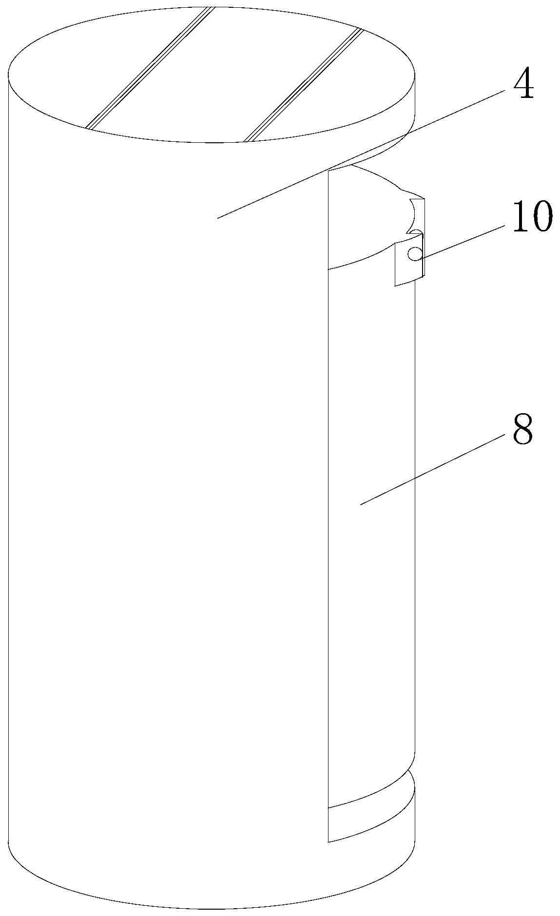
[0021] see Figure 2-5 , an easy-to-control centrifugal vibrating rod, comprising a vibrating rod housing 1, a flexible shaft 2 and a shaft coupling 3, the lower end of the shaft coupling 3 is connected to an adjustable rotating shaft 4, and the upper end of the outer wall of the adjustable rotating shaft 4 is fixed Connect the limited block 5, the adjustable shaft 4 is sleeved with a fixed bearing 9 and a sliding bearing 11, and the sliding bear...


PUM


Abstract

The invention relates to the technical field of concrete equipment, and discloses a centrifugal vibrating rod easy to control. The centrifugal vibrating rod easy to control comprises a vibrating rod shell, a flexible shaft and a shaft connector, the lower end of the shaft connector is in transmission connection with an adjustable rotation shaft, and a limiting block is fixedly connected to the upper end of the outer side wall of the adjustable rotation shaft. According to the centrifugal vibrating rod easy to control, the relative positions between centrifugal blocks and a hinge rod are controlled through a driving rod, and then vibration output is controlled; as quite a long operation time is needed for vibrating rod transferring in the actual engineering operation, the centrifugal blocksare close to the hinge rod in the transferring process, vibration output is reduced, therefore, wear is reduced, the service life of the vibrating rod is prolonged, and meanwhile noise output is reduced; and when the vibrating rod is inserted into concrete, the output vibration magnitude can be appropriately adjusted, influences of the vibrating rod on the concrete in the sinking process are morecontrollable, especially when the inserting position is located at the corners or is close to steel bars, and then the vibrating quality of the concrete is improved.

Description

technical field [0001] The invention relates to the technical field of concrete equipment, in particular to an easy-to-control centrifugal vibrating rod. Background technique [0002] see figure 1 When pouring concrete components, a vibrator must be used to remove the air bubbles and tamp them to make the concrete densely combined and eliminate the phenomenon of concrete honeycomb denseness. The vibration principle of the vibrating rod has eccentric type and planetary type. The rotating shaft with eccentric mass rotates at high speed, and the centrifugal force that changes direction is transmitted to the vibration shell through the bearing, thereby generating vibration. However, in this way, a large friction force will be generated between the bearing and the vibration shell, and its service life is limited. [0003] Secondly, the current construction site has high requirements for noise, and when the vibrating rod vibrates, it will generate a lot of noise, especially when ...

Claims


Application Information

Patent Timeline
Patent Type & Authority Applications(China)
IPC IPC(8): E04G21/08
CPCE04G21/08
Inventor 魏双清
Owner ANHUI CHUNGU 3D PRINTING INTELLIGENT EQUIP IND TECH RES INST CO LTD
Learn More