A kind of detachable paint brush production process
A production process and paint brush technology, applied in the field of paint brushes, can solve the problems of unenvironmental protection, energy saving, waste of handles, etc., and achieve the effects of being conducive to recycling, improving utilization rate, and simple assembly
- Summary
- Abstract
- Description
- Claims
- Application Information
AI Technical Summary
Problems solved by technology
Method used
Image
Examples
Embodiment 1
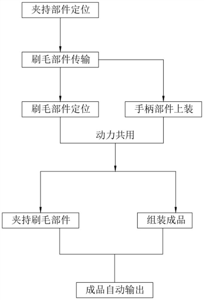
[0092] like Figure 16 As shown, a detachable paint brush production process, including:
[0093] Step 1, positioning the clamping part, manually placing the clamping part 32 on the mounting post 312 of the support assembly 31, and using the mounting post 312 to achieve positioning;
[0094] In step 2, the bristle member is transported, one end of the bristle member 13 is located on the first transmission assembly 11 and the other end is suspended outside the first transmission assembly 11 until it is transferred to the second transmission assembly 12 and suspended outside the first transmission assembly 11 The bristle member 13 is transmitted on the second transmission assembly 12;
[0095] Step 3, the bristle component is positioned, the pressing component 33 is activated, the insertion rod 334 of the pressing component 33 is pressed down on the lower clamping plate 3221 of the clamping component 32 through the insertion hole 335, and the bristle component 13 is transferred...
Embodiment 2
[0110] Referring to the first embodiment, an automatic output device for paint brushes of the present invention is described.
[0111] like figure 1 As shown, an automatic output device for paint brushes, comprising:
[0112] A bristle feeding device 1, the bristle feeding device 1 includes a first transmission assembly 11 and a second transmission assembly 12 arranged on one side of the first transmission assembly 11, and one end of the bristle component 13 is located on the first transmission assembly 11 and the other end is located on the second transmission assembly 12;
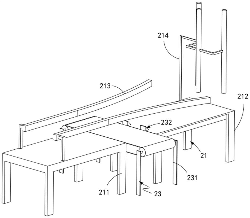
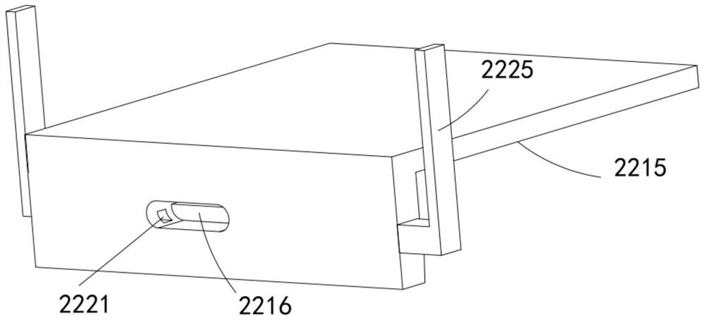
[0113] The handle feeding device 2, the handle feeding device 2 includes a third transmission component 21 arranged perpendicular to the transmission direction of the first transmission component 11, and a push component slidably arranged along the transmission direction of the third transmission component 21 22 and a feeding assembly 23 arranged perpendicular to the third conveying assembly 21 and alon...
Embodiment 3
[0167] like Figure 15 As shown, the same or corresponding parts as those in the second embodiment are marked with the corresponding reference numerals as in the second embodiment. For the sake of brevity, only the differences from the first embodiment are described below. The difference between the third embodiment and the first embodiment is:
[0168] further, as Figure 15 As shown, the transmission assembly 34 includes:
[0169] a transmission rod a341, the transmission rod a341 is fixedly connected with the driving rod 333 and is arranged perpendicular to it;
[0170] A switching member 342, the switching member 342 includes a rack a3421 fixedly connected to the transmission rod a341 and arranged vertically, a frame e3422 installed on the frame d331, and a rotating shaft c3423 rotatably arranged on the frame e3422 , a gear a3424 meshed with the rack a3421 and fixedly arranged with the rotating shaft c3423, a gear b3425 arranged on the side of the gear a3424 and fixed w...
PUM
 Abstract
Description
Claims
Application Information
 - Generate Ideas
- Intellectual Property
- Life Sciences
- Materials
- Tech Scout
- Unparalleled Data Quality
- Higher Quality Content
- 60% Fewer Hallucinations
Browse by: Latest US Patents, China's latest patents, Technical Efficacy Thesaurus, Application Domain, Technology Topic, Popular Technical Reports.
© 2025 PatSnap. All rights reserved.Legal|Privacy policy|Modern Slavery Act Transparency Statement|Sitemap|About US| Contact US: help@patsnap.com


