Automatic batch kebab penetration machine
A skewering machine and batch technology, which is applied in the fields of skewering meat on skewers, confectionery, confectionary industry, etc. It can solve the problems of skewing due to the verticality difference and the limited space for placing materials and placing labels. , Inability to adapt to different lengths and specifications of string products, etc., to achieve the effect of large operating space
- Summary
- Abstract
- Description
- Claims
- Application Information
AI Technical Summary
Problems solved by technology
Method used
Image


Examples
specific Embodiment approach 1
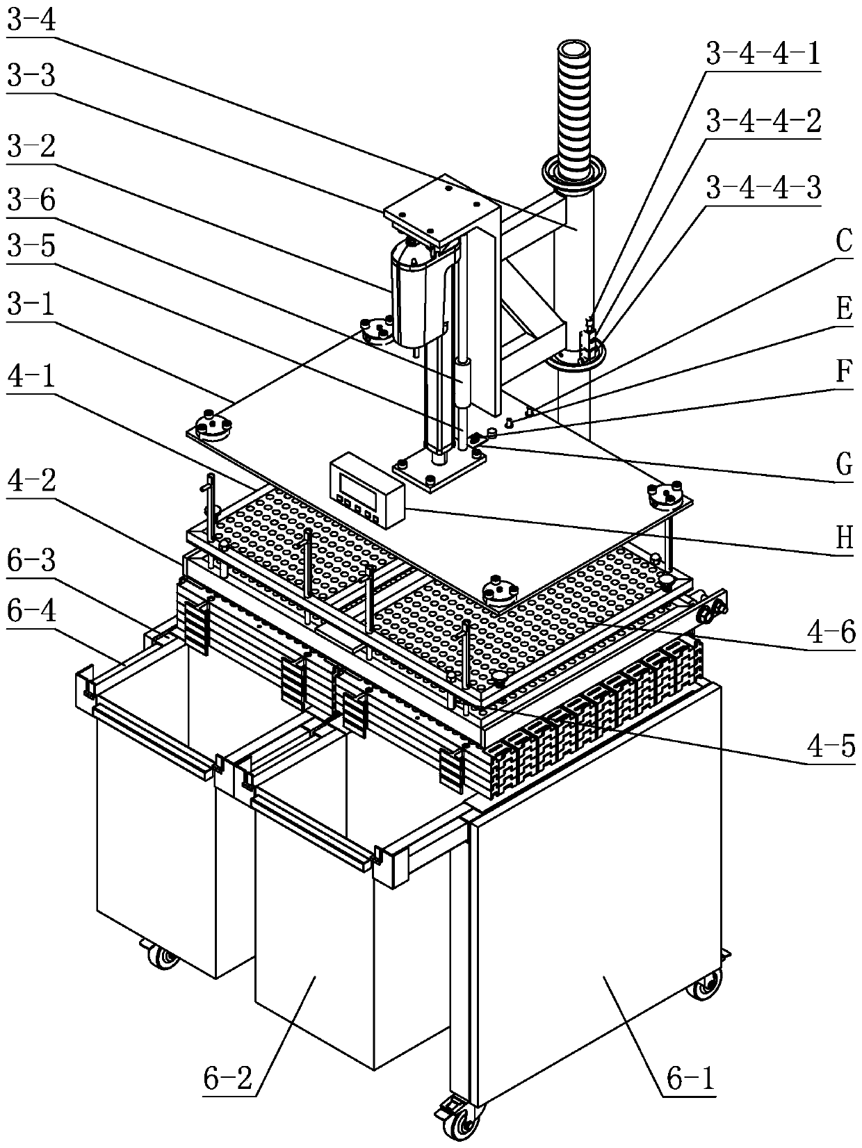
[0021] Specific implementation mode one: combine figure 1 , figure 2 with Figure 8 to Figure 11 Describe this embodiment, an automatic batch threading machine of this embodiment, which includes a body support frame 1, a machine head optical axis column 2, a sign pressing component 3, a sign limiting component 4, a material placement plate group 5 and a finished product storage box 6. The optical axis column 2 of the machine head is fixed on the rear side wall of the body support frame 1 along the vertical direction, the material placement plate group 5 is horizontally placed on the body support frame 1, and the finished product storage box 6 is arranged directly below the material placement plate group 5 , the label pressing assembly 3 and the label limiting assembly 4 are sequentially arranged directly above the material setting plate group 5 from top to bottom, the label pressing assembly 3 and the label limiting assembly 4 are respectively rotatably connected with the op...
specific Embodiment approach 2
[0025] Specific implementation mode two: combination figure 2 Describe this embodiment. The push rod connection assembly 3-4 of this embodiment includes a first optical shaft sleeve 3-4-1, an upper limit handwheel 3-4-2, a lower limit handwheel 3-4-3, and a machine head Rotation limiter 3-4-4 and Z-type connecting bracket 3-4-5, upper limit handwheel 3-4-2, first optical shaft sleeve 3-4-1 and lower limit handwheel 3-4-3 Set on the optical axis column 2 of the machine head in sequence from top to bottom, the upper limit handwheel 3-4-2 and the lower limit handwheel 3-4-3 are respectively threaded with the optical axis column 2 of the machine head, the first optical axis The sleeve 3-4-1 is connected with the lower limit handwheel 3-4-3 through the head rotation limiter 3-4-4, and one end of the Z-shaped connecting bracket 3-4-5 is connected to the first optical shaft sleeve 3-4-1 is fixedly connected, and the other end of the Z-shaped connecting bracket 3-4-5 is fixedly conn...
specific Embodiment approach 3
[0027] Specific implementation mode three: combination Image 6 To illustrate this embodiment, the sign limiting plate frame connector 4-3 of this embodiment includes an optical axis fixing ring 4-3-1, a second optical axis sleeve 4-3-8, a first rotating shaft 4-3-2, a second A shaft sleeve 4-3-3, a second shaft 4-3-4, a second shaft sleeve 4-3-5, two frame lock nuts 4-3-6 and two frame limit end plates 4-3 -7, the second optical axis sleeve 4-3-8 and the optical axis fixing ring 4-3-1 are sequentially set on the optical axis of the machine head between the body support frame 1 and the lower limit handwheel 3-4-3 from top to bottom On the column 2, the second optical shaft sleeve 4-3-8 is slidably matched with the optical axis column 2 of the machine head, the optical axis fixing ring 4-3-1 is connected with the optical axis column 2 of the machine head through set screws, and the first rotating shaft The sleeve 4-3-3 is perpendicular to the second optical shaft sleeve 4-3-8 ...
PUM
 Abstract
Description
Claims
Application Information
 - R&D
- Intellectual Property
- Life Sciences
- Materials
- Tech Scout
- Unparalleled Data Quality
- Higher Quality Content
- 60% Fewer Hallucinations
Browse by: Latest US Patents, China's latest patents, Technical Efficacy Thesaurus, Application Domain, Technology Topic, Popular Technical Reports.
© 2025 PatSnap. All rights reserved.Legal|Privacy policy|Modern Slavery Act Transparency Statement|Sitemap|About US| Contact US: help@patsnap.com