Installation method and hydraulic system of blast furnace air inlet pipeline

An installation method and technology of hydraulic system, applied in the direction of tuyere, flange connection, fluid pressure actuating device, etc., can solve the problems of high labor intensity, long tightening time, low maintenance efficiency, etc., so as to improve maintenance efficiency and save time. Effortless threaded connection to avoid air leakage

Active Publication Date: 2021-06-29
PANGANG GRP XICHANG STEEL & VANADIUM CO LTD
View PDF6 Cites 0 Cited by
  • Summary
  • Abstract
  • Description
  • Claims
  • Application Information

AI Technical Summary

Problems solved by technology

During this process, when tightening eight M42 bolts with an M42 extension wrench, at least four people need to apply force to the extension wrench at the same time to tighten the bolts on the flange one by one, that is, The air pipe flange and the downcomer flange are gradually tightly connected by manually screwing the bolts to compress the metal gasket. This operation method is not only labor-intensive but also takes a long time to tighten, and the maintenance efficiency is relatively low, which seriously affects the economy of the blast furnace. benefit and social benefit

Method used


Image

  • Installation method and hydraulic system of blast furnace air inlet pipeline
  • Installation method and hydraulic system of blast furnace air inlet pipeline
  • Installation method and hydraulic system of blast furnace air inlet pipeline

Examples


Embodiment Construction

[0042] The invention provides a method for installing the blast furnace air inlet pipeline, which can save time and labor for the maintenance of the blast furnace inlet pipeline, and significantly improve the maintenance efficiency.

[0043]The following will clearly and completely describe the technical solutions in the embodiments of the present invention with reference to the accompanying drawings in the embodiments of the present invention. Obviously, the described embodiments are only some, not all, embodiments of the present invention. Based on the embodiments of the present invention, all other embodiments obtained by persons of ordinary skill in the art without making creative efforts belong to the protection scope of the present invention.

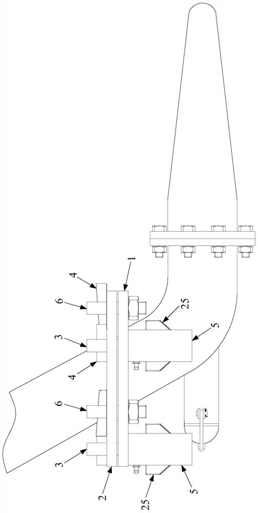
[0044] Such as figure 1 As shown, the embodiment of the present invention provides a method for installing the air inlet pipeline of a blast furnace, which is mainly used to realize the sealed connection between the air duct and t...


PUM


Abstract

The application discloses an installation method and a hydraulic system of a blast furnace air inlet pipeline, including the following steps: connecting the flange of the air pipe and the flange of the downcomer; making the piston rod of the hydraulic cylinder in the extended state pass through the air pipe flange and the downcomer flange, and connect the locking piece on the piston rod to prevent the piston rod from coming out of the threaded hole; control the contraction of the piston rod to make the air pipe flange under the extrusion of the locking piece and the cylinder Sealed connection with the flange of the downcomer and maintain a sealed connection; except for the threaded hole passed by the piston rod, the rest of the threaded holes in the flange of the air pipe and the flange of the downcomer are passed through by bolts, and the bolts are pre-tightened to the air pipe Flange and downcomer flange; control the extension of the piston rod so that the hydraulic cylinder releases the extrusion of the air duct flange and the downcomer flange, so that the air duct flange and the downcomer flange remain under the bolted connection Sealed connection state. The above-mentioned installation method uses a hydraulic cylinder to press the two butt flanges, which saves time and effort during the installation process and improves the maintenance efficiency.

Description

technical field [0001] The invention relates to the technical field of blast furnace ironmaking, in particular to a method for installing an air inlet pipeline of a blast furnace, and also relates to a hydraulic system suitable for the installation method of the air inlet pipeline of a blast furnace. Background technique [0002] The air inlet pipeline of the blast furnace generally adopts an air duct to connect the downcomer below the annular surrounding pipe of the blast furnace body to send hot blast into the furnace for blast furnace smelting. Due to the high smelting intensity and temperature of the blast furnace, it is easy to cause the three sets of tuyeres at the air inlet of the blast furnace to burn out. At the same time, the air duct is a fragile part. The superposition of these factors leads to the frequent shutdown of the blast furnace to replace the three sets of tuyeres. and air ducts. For some blast furnaces, due to the limited operating space, the disassemb...

Claims


Application Information

Patent Timeline
Patent Type & Authority Patents(China)
IPC IPC(8): F16L23/024F16L23/00F15B11/00F15B15/14C21B7/16
CPCC21B7/16F15B11/00F15B15/14F16L23/003F16L23/024
Inventor 郭先军叶祥华郭建生杜刚郭自力薛峰肖成广
Owner PANGANG GRP XICHANG STEEL & VANADIUM CO LTD
Why Eureka
Try Eureka