
Single-layer broadband filtering function fused high-gain CPW differential antenna

A high-gain, single-layer technology, applied in the field of filter antennas and high-gain CPW differential antennas, can solve the problems of no filter function, complex structure, and no filter zero point, etc., and achieve the effect of enhanced filter performance, good performance, and wide filter bandwidth

Active Publication Date: 2020-02-07
BEIJING UNIV OF POSTS & TELECOMM
View PDF12 Cites 3 Cited by
  • Summary
  • Abstract
  • Description
  • Claims
  • Application Information

AI Technical Summary

Problems solved by technology

[0004] At present, CPW differential feed or differential feed antennas have been studied. The focus of the research is either on the ultra-wideband notch antenna, which has no filtering function, or has no filter zero point generation, and its structure is relatively complicated.

Method used


Image

  • Single-layer broadband filtering function fused high-gain CPW differential antenna
  • Single-layer broadband filtering function fused high-gain CPW differential antenna
  • Single-layer broadband filtering function fused high-gain CPW differential antenna

Examples


Embodiment

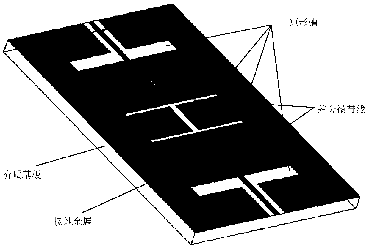
[0079] Set the working center frequency to 3.935GHz, the passband range (|S dd11 |<-10dB) is 3.28GHz-4.59GHz, the maximum gain is 8.16dBi, and the two filter zero positions are 3.07GHz and 4.97GHz respectively.

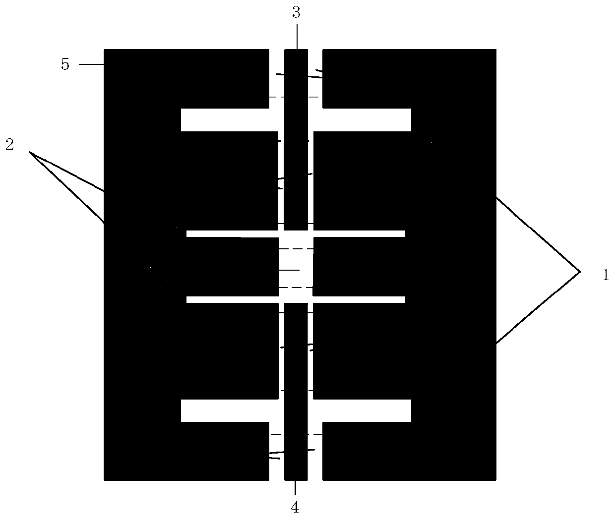
[0080] Among the two pairs of parallel rectangular slots, the second pair of slots 2 produces an upper zero point and has the function of adjusting impedance matching. Its width is 1 mm and its length is 30.4 mm. The first pair of slots 1 produces the lower zero point, which is 4 mm wide and 33.2 mm long.

[0081] The two differential microstrip lines 3 and 4 are used to feed the entire CPW antenna. Considering that the antenna is to be welded to the SMA connector with a characteristic impedance of 50Ω, the value of the input impedance is set to 50Ω, its width is 1.6mm, and its length is 34mm. The ground metal 5 has a width of 55mm and a length of 80mm. The coupling slots 6 and 8 have a width of 0.2 mm and a length of 18 mm. The coupling slots 7 and 9 have a width...


PUM

PropertyMeasurementUnit
thicknessaaaaaaaaaa
sizeaaaaaaaaaa

Abstract

The invention discloses a single-layer broadband filtering function fused high-gain CPW differential antenna, and belongs to the technical field of microwave antennas. The differential antenna is constructed on a single-layer dielectric substrate, and the upper layer of the dielectric substrate is completely coated with copper to obtain grounding metal; the grounding metal is symmetrically etchedalong the center line of the dielectric substrate from the two ends of the dielectric substrate to obtain two sections of first coupling gaps with the same length and the same width, and a first pairof slots parallel to each other and having the same size is symmetrically formed by etching at the ends of the two sections of first coupling gaps; the grounding metal continues to be symmetrically etched along the center line of the dielectric substrate from the first pair of slots to obtain two sections of second coupling gaps with the same length and the same width; a second pair of slots parallel to each other and having the same size is symmetrically formed by etching at the ends of the two sections of second coupling gaps; and finally, the second pair of slots is communicated through a third coupling gap along the center line of the dielectric substrate. The size of a communication system is reduced, and the antenna is suitable for design of more high-performance systems.

Description

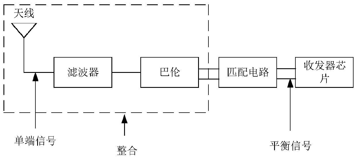
technical field [0001] The invention belongs to the technical field of microwave antennas, and relates to a filter antenna, in particular to a high-gain CPW differential antenna integrated with a single-layer broadband filter function. Background technique [0002] In recent years, research on filter antennas has become more and more popular. The filter antenna combines the design of the filter and the antenna, which solves the problem of difficult impedance matching caused by the independent design of the antenna and filter, and can reduce the size and cost of the system. [0003] In modern microwave and wireless communication systems, compared with single-ended antennas, differential antennas avoid the use of additional baluns when connecting with other radio frequency devices, thereby reducing the size of the system and effectively improving system performance. As the last stage of communication equipment, that is, the radiation unit, the antenna needs circuit feeding, a...

Claims


Application Information

Patent Timeline
Patent Type & Authority Applications(China)
IPC IPC(8): H01Q1/48H01Q1/50
CPCH01Q1/48H01Q1/50
Inventor 吴永乐陈潇潇王卫民杨雨豪
Owner BEIJING UNIV OF POSTS & TELECOMM
Learn More