
Layered conveying mechanism

A conveying mechanism and layered technology, applied in the field of layered conveying mechanism, can solve the problems of low conveying efficiency, low degree of automation and high implementation cost, and achieve the effect of high degree of automation, strong versatility and low implementation cost

Pending Publication Date: 2020-02-07
SHENZHEN ZOWEE SMART MFG CO LTD
View PDF0 Cites 1 Cited by
  • Summary
  • Abstract
  • Description
  • Claims
  • Application Information

AI Technical Summary

Problems solved by technology

[0004] In order to overcome the deficiencies of the prior art, the present invention provides a layered conveying mechanism, which solves the problems of the prior art, such as low degree of automation, low conveying efficiency, high labor cost, easy damage to products, complex structure, high implementation cost, stable Technical defects such as poor performance and poor versatility

Method used


Image

  • Layered conveying mechanism
  • Layered conveying mechanism
  • Layered conveying mechanism

Examples


Embodiment Construction

[0029] The idea, specific structure and technical effects of the present invention will be clearly and completely described below in conjunction with the embodiments and accompanying drawings, so as to fully understand the purpose, features and effects of the present invention. Apparently, the described embodiments are only some of the embodiments of the present invention, rather than all of them. Based on the embodiments of the present invention, other embodiments obtained by those skilled in the art without creative efforts belong to The protection scope of the present invention. In addition, all the connection / connection relationships involved in the patent do not simply refer to the direct connection of components, but mean that a better connection structure can be formed by adding or reducing connection accessories according to specific implementation conditions. The various technical features in the invention can be combined interactively on the premise of not contradict...


PUM


Abstract

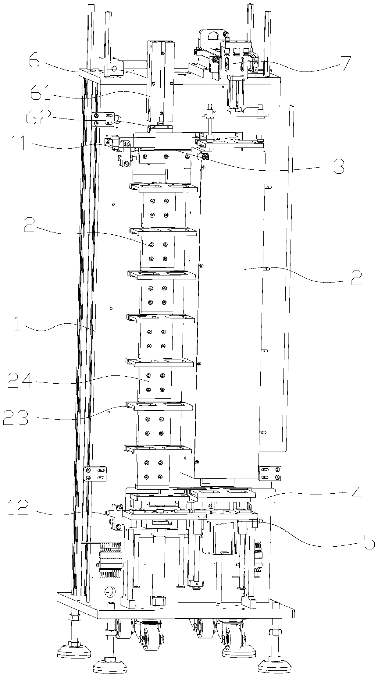
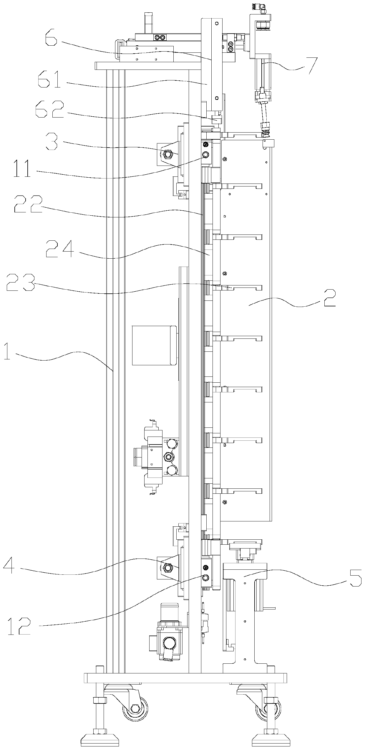
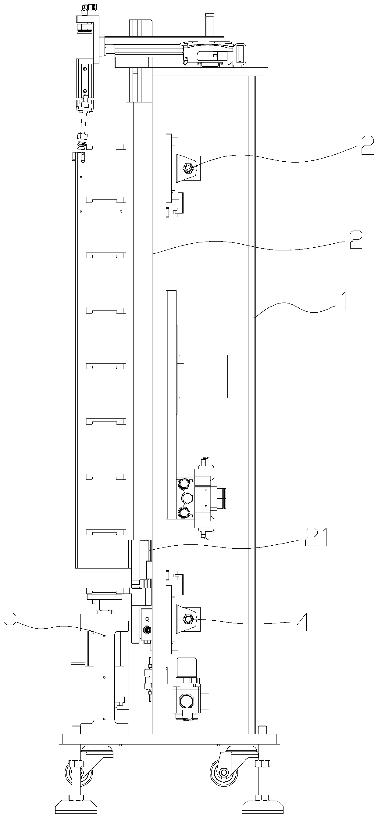
The invention discloses a layered conveying mechanism. The layered conveying mechanism comprises a rack, a circulating assembly, an upper translation assembly, a lower translation assembly, a jackingassembly and a downward pressing assembly, wherein the circulating assembly, the upper translation assembly, the lower translation assembly, the jacking assembly and the downward pressing assembly arearranged on the rack. The circulating assembly comprises two circulating guide rails and a plurality of circulating conveying plates arranged on the circulating guide rails and used for circulating and conveying workpieces. The upper translation assembly is used for conveying the circulating conveying plates on the top of the first circulating guide rails to the top of a second circulating guiderail. The lower translation assembly is used for conveying the circulating conveying plates at the bottom of the second circulating guide rail to the bottom of the first circulating guide rail. The jacking assembly is used for jacking the circulating conveying plates on the first circulating guide rail. The downward pressing assembly is used for pressing the circulating conveying plates on the second circulating guide rail downwards. Compared with the prior art, the layered conveying mechanism has the advantages that the structure is simple, the performance is stable and reliable, the implementation cost is low, the automation degree is high, the labor cost is saved, the production efficiency is improved, and the like.

Description

technical field [0001] The invention relates to a conveying device, in particular to a layered conveying mechanism. Background technique [0002] At present, in the electronic product manufacturing industry, it is necessary to quickly and continuously transport various materials in the production and packaging of products to ensure the continuous production. At this stage, the product feeding is generally manual feeding, which is not only inefficient, but also requires a lot of manpower. The cost is high, and manual material collection is easy to cause bumps, which affects product quality. However, some automatic feeding and receiving equipment have disadvantages such as complex equipment structure, high equipment cost, and poor conveying stability, which seriously affect the further promotion and application of automated conveying equipment; There is no mature conveying mechanism to realize the automatic conveying function, which seriously reduces the conveying efficiency....

Claims


Application Information

Patent Timeline
Patent Type & Authority Applications(China)
IPC IPC(8): B65G47/52B65G47/91
CPCB65G47/52B65G47/912
Inventor 刘鹏
Owner SHENZHEN ZOWEE SMART MFG CO LTD
Learn More