Cleaning device for cleaning a transparent cover of an optical or optoelectronic device

A technology for cleaning equipment and photoelectric equipment, which is applied in the direction of optics, optical components, and vehicle cleaning, and can solve problems such as undesired optical distortion of camera images, unfavorable space utilization, weight and cost, and large cleaning fluids, so as to save the need to close And the effect of controlling equipment, saving consumption and reducing consumption

Pending Publication Date: 2020-01-31
CONTINENTAL AUTOMOTIVE TECH GMBH
View PDF12 Cites 0 Cited by
  • Summary
  • Abstract
  • Description
  • Claims
  • Application Information

AI Technical Summary

Problems solved by technology

[0006] Frequent cleaning intervals result in a correspondingly high consumption of cleaning fluid from limited reserves to be carried
In order to extend the refill intervals, large storage containers must be provided, but this is detrimental to space utilization, weight and cost
[0007] In addition to contamination, simple water droplets on the camera lens can cause undesired optical distortions in the camera image

Method used


Image

  • Cleaning device for cleaning a transparent cover of an optical or optoelectronic device

Examples


Embodiment Construction

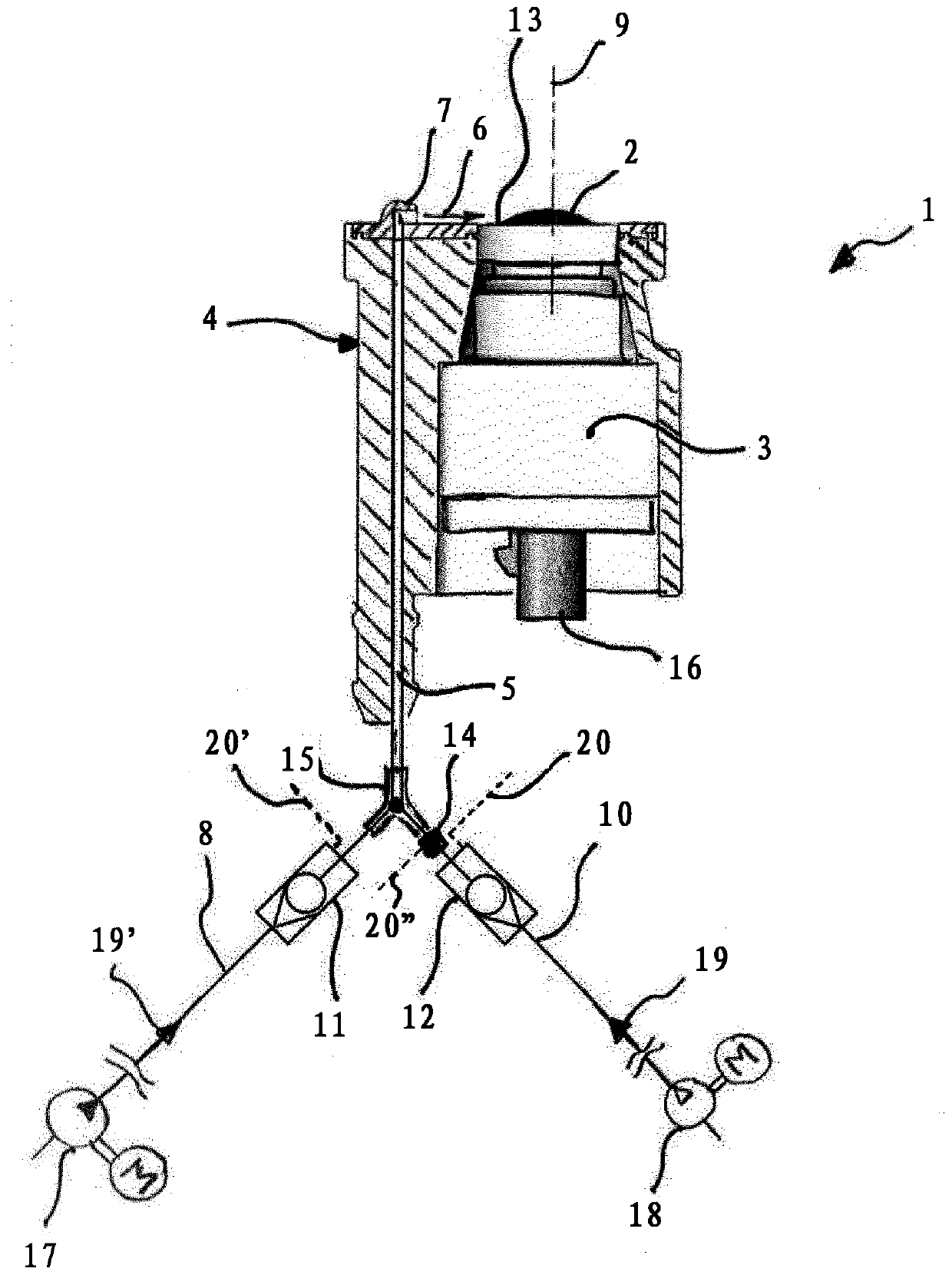
[0025] Arranged in the housing 4 of the cleaning device 1 is an optical device 3 designed as a camera with a transparent element 2 designed as a camera lens. The electrical interface 16 is used to connect the device 3 to one or more power supply means and electronic control units not shown here. The transparent element 2 is curved outwards and has an optical axis 9 .

[0026] Fluid inlet 5 is used to supply cleaning fluid to individual nozzles 7 . Within the present invention, the use of multiple nozzles 7 is allowed at any time.

[0027] The nozzle 7 is designed as a deflector or impingement nozzle. The nozzles form a flat cleaning agent jet 6 which runs transversely to the optical axis 9 in a plane substantially perpendicular to the optical axis. The cleaning agent jet 6 is oriented here in such a way that it hits approximately at the radially outer edge 13 of the transparent element 2 .

[0028] In this case, a property of the fluid called the Coanda effect in hydrodyna...


PUM


Abstract

The invention relates to a cleaning device (1) for cleaning a transparent element (2) of an optical or optoelectronic device (3) with a fluid cleaning agent, comprising a housing (4) in which the device (3) is arranged, at least one fluid inlet (5) which is arranged in the housing (4), and at least one nozzle (7) which is supplied from the fluid inlet (5). The nozzle (7) is designed to deflect a cleaning agent jet (6) onto the transparent element (2), and the jet direction of the cleaning agent jet (6) is provided substantially transversely to an optical axis (9) of the transparent element (2). The aim of the invention is to improve the cleaning power with a reduced consumption of cleaning liquid. According to the invention, this is achieved in that the fluid inlet (5) is designed for a throughflow of a cleaning liquid out of a hydraulic channel (8) and compressed air out of a pneumatic channel (10), wherein the hydraulic channel (8) has a hydraulic nonreturn valve (11), and the pneumatic channel (10) has a pneumatic nonreturn valve (12), said nonreturn valves (11, 12) opening the channels (8, 10) in the direction of the nozzle (7) and blocking the channels in the opposite direction.

Description

technical field [0001] The invention relates to a cleaning device for cleaning transparent elements of optical or optoelectronic devices, in particular camera lenses, and to an optical detection system for arrangement in a vehicle, comprising one or more Cleaning equipment for optoelectronic equipment. Background technique [0002] In motor vehicles, assistance systems with sensors are increasingly being installed today, which assist the vehicle user when driving the vehicle and at the same time reliably detect and monitor the vehicle's surroundings at all times. [0003] To this end, such assistance systems include optical or optoelectronic devices, such as in particular cameras, but also laser- or infrared-based sensors installed in the outer area of ​​the vehicle. The basic functions of such devices are diverse and range from simple assistance functions, such as displaying areas covered by the vehicle on a display and parking assistance, up to providing input data for au...

Claims


Application Information

Patent Timeline
Patent Type & Authority Applications(China)
IPC IPC(8): B60S1/48B60S1/52B60S1/54B60S1/56G02B27/00
CPCB60S1/48B60S1/52B60S1/54B60S1/56G02B27/0006G02B27/00
Inventor T·哈恩
Owner CONTINENTAL AUTOMOTIVE TECH GMBH
Why Eureka
Try Eureka