
Radio frequency interconnection method for TR assembly and antenna array plane

An antenna array and component technology, applied in the microwave field, can solve problems such as inconvenient disassembly, testing and maintenance, large radio frequency interconnection size, and difficult KK positioning, etc., to achieve the effect of ensuring long-term reliability, good air tightness, and simple process

Inactive Publication Date: 2020-01-31
10TH RES INST OF CETC
View PDF5 Cites 9 Cited by
  • Summary
  • Abstract
  • Description
  • Claims
  • Application Information

AI Technical Summary

Problems solved by technology

The above-mentioned three-piece interconnection method can realize the airtightness of TR components, but the size of the radio frequency interconnection is large, and KK positioning is difficult during large-scale array integration, and it is easy to be damaged when plugging and unplugging
The above-mentioned fuzzy button radio frequency interconnection method cannot achieve the airtightness of TR components alone, and requires welding or laser sealing on the outer cover plate of the subarray for one radial circle
If a fault occurs under this interconnection scheme, it cannot be easily disassembled for testing and maintenance

Method used


Image

  • Radio frequency interconnection method for TR assembly and antenna array plane
  • Radio frequency interconnection method for TR assembly and antenna array plane

Examples


Embodiment Construction

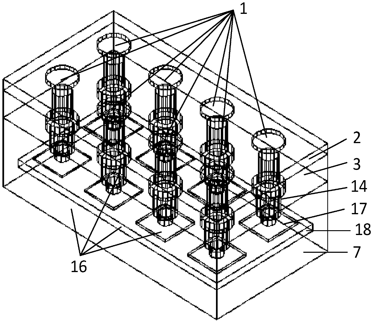
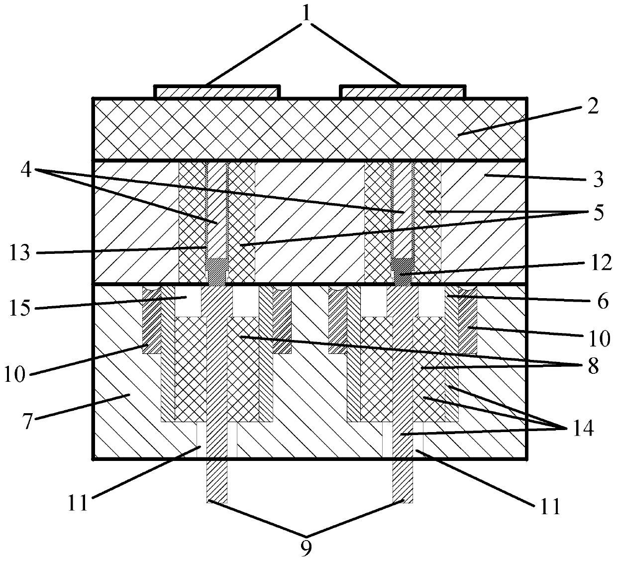
[0014] refer to figure 1 , figure 2 . According to the present invention, the patch antenna 1 arranged and distributed in a linear array is fixed on the antenna-carrying medium substrate 2, and the antenna-carrying medium substrate 2 presses the outer conductor 7 of the TR component structural member tightly through the button metal substrate 3; vertically corresponds to the patch antenna 1 The polymer-based composite dielectric tube 5 on the lower front passes through the button metal substrate 3, and is closely attached to the end face of the radio frequency connection insulator 14; the insulator solder 10 is used to integrally sinter the outer conductor 7 of the structural part of the TR assembly The radio frequency connection insulator 14, corresponding to the polymer-based composite dielectric tube 5, is assembled in the stepped hole of the outer conductor 7 of the TR component structure; the button inner core 4 passes through the button inner core sleeve 13, and is tig...


PUM


Abstract

The invention discloses a radio frequency interconnection method for a TR assembly and an antenna array plane and aims to provide a radio frequency interconnection method which is high in channel density, good in air tightness and easy to disassemble, assemble and maintain. According to the technical schemes of the invention, an antenna bearing dielectric substrate is tightly pressed on a radio frequency insulator metal substrate through a fuzz button metal substrate; polymer-based composite dielectric tubes vertically corresponding to the lower array surfaces of patch antennas penetrate through the fuzz button metal substrate and are tightly attached to the end surfaces of radio frequency connection insulators; the radio frequency connection insulators integrally sintered on a TR assemblystructural member outer conductor through insulator solder are assembled in the stepped holes of the TR assembly structural member outer conductor in a manner that the radio frequency connection insulators are corresponding to the polymer-based composite dielectric tubes; fuzz button inner cores are tightly pressed on T-shaped probes, and insulator inner conductors are connected with the interconnection end of the TR assembly through glass dielectric insulation bodies filling insulator outer conductor holes and air coaxial matching cavities which are arranged below the glass dielectric insulation bodies and are in sealed matching with the glass, so that a coaxial transmission structure is formed.

Description

technical field [0001] The invention belongs to the field of microwave technology, and in particular relates to a radio frequency interconnection method of a high-density hermetic TR component and an antenna array. Background technique [0002] As phased array antennas enter the millimeter wave frequency band, the integration level of the array level is getting higher and higher, and the spacing between antenna array elements is also shrinking. The element spacing of the phased array antenna above 30GHz will basically be compressed within 5mm. The phased array antenna is equipped with antenna array, feeder, TR components, power supply, cooling system and many other equipment, which is the most complex part of the whole radar. The equipment in the radar phased array antenna is connected with a large number of cables and connectors. Once water seeps into the array, it may cause a short circuit, causing the electrical performance of the antenna to decline or even fail as a who...

Claims


Application Information

Patent Timeline
IPC IPC(8): H01Q1/38H01Q1/50H01Q21/00H01Q21/06
CPCH01Q1/38H01Q1/50H01Q21/0006H01Q21/065
Inventor 朱贵德熊文毅王彪蓝海
Owner 10TH RES INST OF CETC
Learn More