A water removal device for atmospheric and vacuum in petroleum refining
An atmospheric and vacuum refining technology, applied in the direction of mechanical dehydration/emulsion breaking, etc., can solve the problems that do not conform to the concept of energy saving and environmental protection, consume a lot of electric energy, and have a large workload, so as to achieve crude oil precipitation, increase temperature, and increase efficiency effect
- Summary
- Abstract
- Description
- Claims
- Application Information
AI Technical Summary
Problems solved by technology
Method used
Image
Examples
Embodiment 1
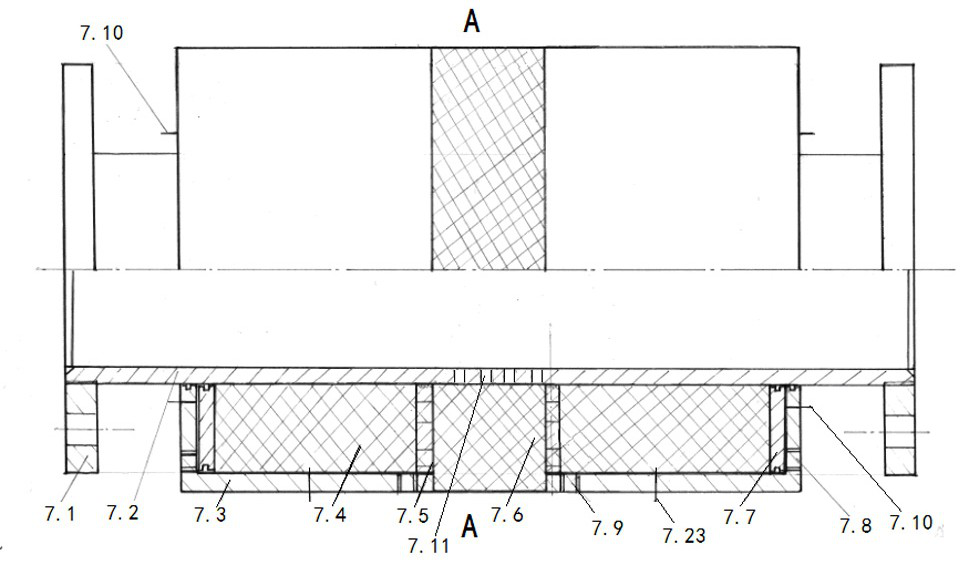
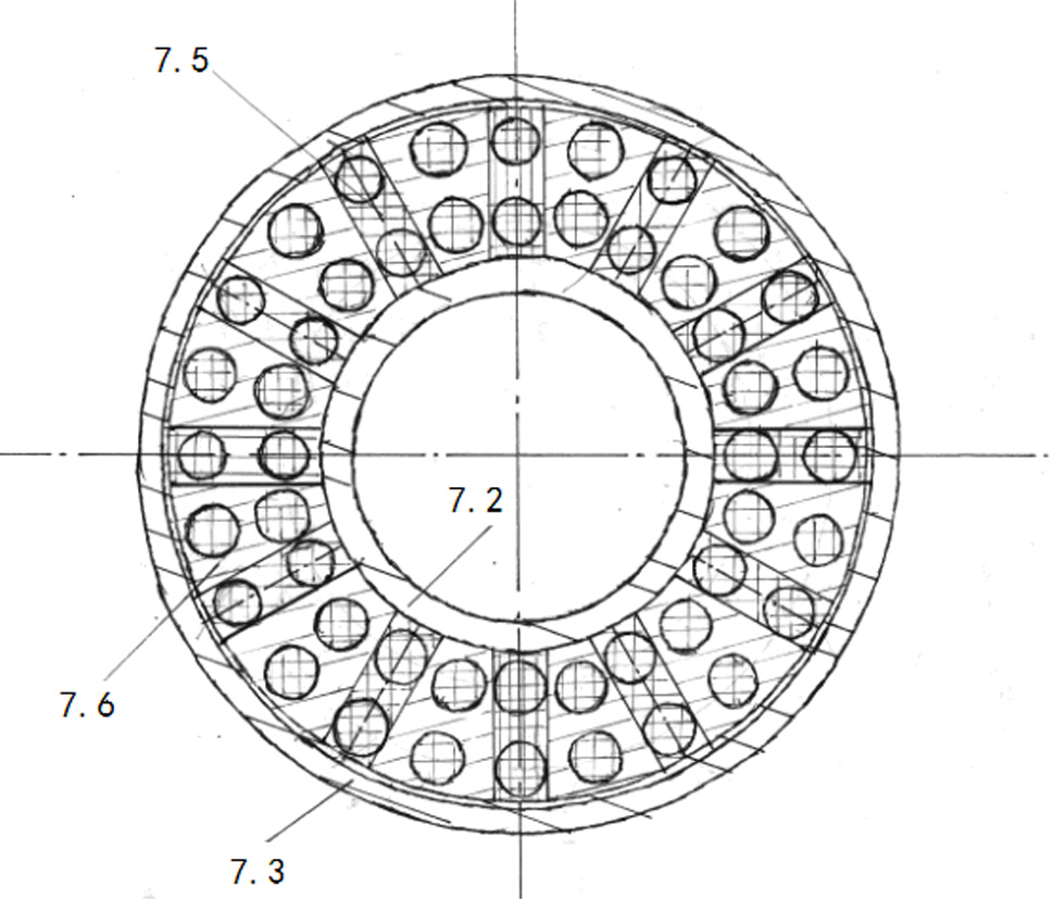
[0025] Embodiment 1, with reference to attached figure 2 , the present invention refers to a water removal device for atmospheric and decompression in petroleum refining, including connecting flange 7.1, central screen pipe 7.2, power cylinder liner 7.3, water storage expansion rubber 7.4, rubber bearing frame 7.5, water absorption expansion rubber 7.6 , pressurizing piston 7.7, drain hole 7.9, pressure sensor 7.10, the two ends of the central screen pipe 7.2 are respectively provided with connecting flanges 7.1 for connecting with the main oil supply line 1, and the middle part of the central screen pipe 7.2 is provided with Water-absorbing screen hole; a power cylinder liner 7.3 is installed and fixed on the outside of the center screen tube 7.2, and the power cylinder liner 7.3 is provided with a liquid inlet hole 7.8 and a liquid discharge hole 7.9, and the cavity formed between the power cylinder liner 7.3 and the center screen tube 7.2 Water storage expansion rubber 7.4...
Embodiment 2
[0044]Embodiment 2, the difference between the present invention and embodiment 1 is:
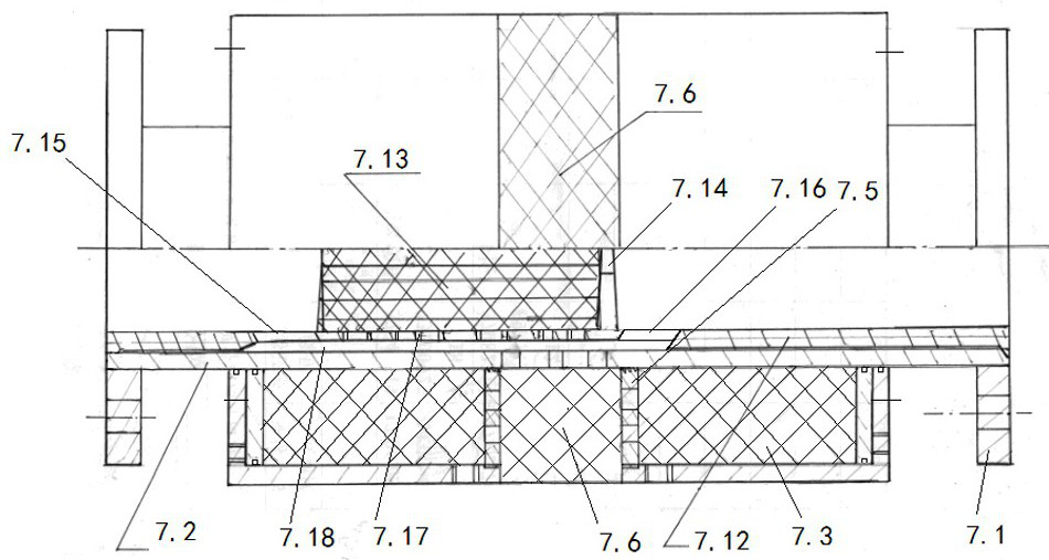
[0045] Refer to attached Figure 4 The inner cavity of the central screen tube 7.2 of the present invention is provided with an oil-absorbing core tube, and the oil-absorbing core tube includes a core tube main body 7.12, an oil-expandable rubber 7.13, a rubber support frame 7.14, a side oil inlet 7.15, and a side oil outlet 7.16 , side oil suction hole 7.17, liquid passage 7.18, core tube sleeve 7.19, core tube piston 7.20, core tube liquid inlet hole 7.21, core tube pressure sensor 7.22, and the inner cavity of the core tube main body 7.12 is provided with two sets of rubber support frames 7.14 , and connect the open core tube sleeve 7.19 at the right end to the outside of the rubber support frame 7.14 on the left side, a core tube piston 7.20 and an oil-expandable rubber 7.13 are arranged in the core tube sleeve 7.19, and the oil-expandable rubber 7.13 Fill the cavity between the core t...
Embodiment 3
[0047] Embodiment 3, the difference between the present invention and embodiment 2 is:
[0048] Refer to attached Figure 5 , in order to improve the water absorption capacity, the power cylinder liner of the present invention can be used as a whole, and the middle part is provided with a water absorption protrusion 7.24, so that the volume of the inner cavity is increased, and more water-absorbing swelling rubber is installed, and the water absorption effect is better Some; and power cylinder liner is connected to the outside of rubber load-bearing frame 7.5 by thread, and rubber load-bearing frame 7.5 is welded on the outer wall of central screen pipe, and two rubber load-bearing frames 7.5 are positioned at the both sides of water-absorbing screen hole.
PUM
 Abstract
Description
Claims
Application Information
 - R&D
- Intellectual Property
- Life Sciences
- Materials
- Tech Scout
- Unparalleled Data Quality
- Higher Quality Content
- 60% Fewer Hallucinations
Browse by: Latest US Patents, China's latest patents, Technical Efficacy Thesaurus, Application Domain, Technology Topic, Popular Technical Reports.
© 2025 PatSnap. All rights reserved.Legal|Privacy policy|Modern Slavery Act Transparency Statement|Sitemap|About US| Contact US: help@patsnap.com


