
Displacement testing system and displacement testing method

A test system and test method technology, applied in the test field, can solve problems such as circumferential displacement measurement failure, product reprocessing, and product destructiveness, and achieve low product destructiveness, strong sense of reality, and simple and easy operation Effect

Pending Publication Date: 2020-01-14
GENERAL ENG RES INST CHINA ACAD OF ENG PHYSICS
View PDF0 Cites 2 Cited by
  • Summary
  • Abstract
  • Description
  • Claims
  • Application Information

AI Technical Summary

Problems solved by technology

[0003] Traditional displacement measurement uses differential displacement sensors, eddy current sensors, laser displacement meters, etc. These devices can only measure displacement changes in one direction, and the volume is relatively large. In actual testing, there is a lot of product reprocessing, which is relatively destructive to the product. Satisfy the radial displacement measurement of the structure, but the measurement of the circumferential displacement is basically invalid

Method used


Image

  • Displacement testing system and displacement testing method
  • Displacement testing system and displacement testing method
  • Displacement testing system and displacement testing method

Examples


Embodiment Construction

[0049] The present invention will be further described below in conjunction with accompanying drawing:

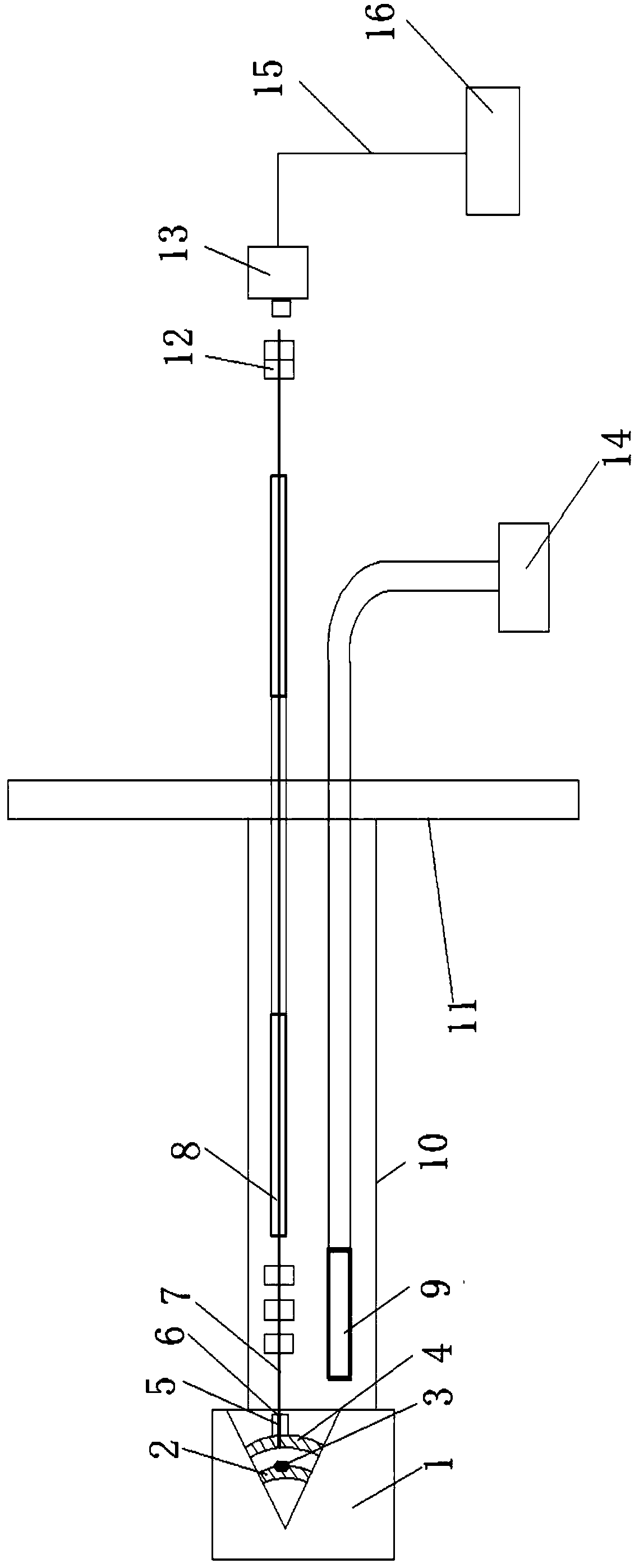
[0050] Such as figure 1 shown;

[0051] Displacement testing system, including:

[0052] Centrifuge; the centrifuge includes a hanging basket 1, a centrifuge arm 10, and a main shaft 11, and the test product is placed in the hanging basket 1; the outer wall of the test product is provided with openings;

[0053] A micro-fiber probe 5; one end of the micro-fiber probe 5 is placed in the opening of the test product;

[0054] The mounting bracket 6, the micro-fiber probe 5 is also fixed on the mounting bracket 6;

[0055] Feature point calibration label 3; feature point calibration label 3 is set on the upper structure and lower structure of the test product;

[0056] The micro-fiber insertion part 7; the micro-fiber insertion part 7 is fixedly installed along the centrifuge arm; and protective measures are taken;

[0057] Imaging and image acquisition equipment 13;

[0...


PUM


Abstract

The invention discloses a displacement testing system which comprises a centrifugal machine, a micro optical fiber probe, a feature point calibration label, a micro optical fiber insertion part, a development and image acquisition device, a cold light source, an optical fiber image transmission bundle, an objective lens, an ocular lens, a network cable and an industrial personal computer. In addition, a displacement testing method comprises the steps of calibration label image acquisition, calibration image processing, displacement / pixel parameter calculation, radial / circumferential displacement image acquisition, detection parameter setting, measurement image processing and displacement display storage. According to the invention, the optical fiber endoscope is applied to a centrifugal dynamic test task and advantages of the optical fiber endoscope are brought into full play. Compared with the traditional displacement measurement mode, the disclosed displacement testing system and displacement testing method have the following advantages: the product destructiveness is low; in-situ test is basically realized; the operation is easy and feasible; the displacement is measured by utilizing an optical imaging technology; and the precision and accuracy of displacement measurement can be improved by further mining and developing the image processing algorithm and technology and the precision can reach a plurality of micro levels at most.

Description

technical field [0001] The invention belongs to the technical field of testing, and in particular relates to a displacement testing system and a displacement testing method. Background technique [0002] In the environmental adaptability test of complex structure products, it is often necessary to detect the radial and circumferential displacement of the structure, and understand the dynamic response law of the corresponding displacement, so as to improve the scientific evaluation and prediction ability of the equipment performance change, and at the same time, it is required to reduce the impact of the detection device on the product. detection damage. Therefore, there is an increasingly strong need to develop a long-distance, low-damage, high-precision displacement testing system and to carry out related testing technology research. [0003] Traditional displacement measurement uses differential displacement sensors, eddy current sensors, laser displacement meters, etc. T...

Claims


Application Information

Patent Timeline
Patent Type & Authority Applications(China)
IPC IPC(8): G01B11/02
CPCG01B11/02
Inventor 范庆辉文勇黄海莹张荣凌明祥周东代明香刘丹峰
Owner GENERAL ENG RES INST CHINA ACAD OF ENG PHYSICS
Learn More