
Welding measuring device and welding method

A measuring device and welding method technology, applied in the field of welding, can solve problems such as the inability to meet the needs of changing monitoring points at any time, difficulty in completing armored thermocouples, and inaccurate temperature measurement, so as to avoid glue residue, realize real-time comparison, Avoid the effect of degaussing

Pending Publication Date: 2020-01-14
POWERCHINA SEPCO1 ELECTRIC POWER CONSTR CO LTD
View PDF12 Cites 0 Cited by
  • Summary
  • Abstract
  • Description
  • Claims
  • Application Information

AI Technical Summary

Problems solved by technology

[0003] The inventors found that when controlling the heat treatment temperature, the commonly used temperature measuring devices are more inconvenient for welding related to thermal power plants: when using far-infrared temperature measuring devices, it is necessary to ensure a specific measurement distance, and it is easily affected by environmental factors. The impact on the bright or polished metal surface such as the outer wall of the pipe will lead to inaccurate temperature measurement; when using armored thermocouples for temperature measurement, it is necessary to ensure that the thermocouple is in contact with the object to be measured, so the armored The thermocouple is bound on the weldment. For the high-altitude welding operation of large-scale pipeline equipment related to thermal power plants, the binding of the armored thermocouple is difficult to complete with one hand, and some large-diameter pipelines need to rely on other auxiliary tools to achieve installation and temperature measurement. ; It is difficult to arrange multi-points according to the needs, and cannot meet the needs of being arranged at any position and changing monitoring points at any time

Method used


Image

  • Welding measuring device and welding method
  • Welding measuring device and welding method

Examples


Embodiment 1

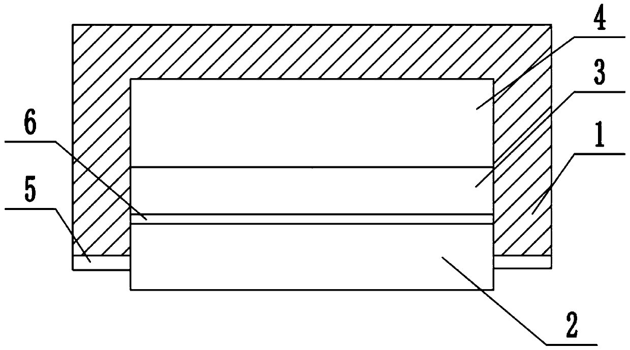
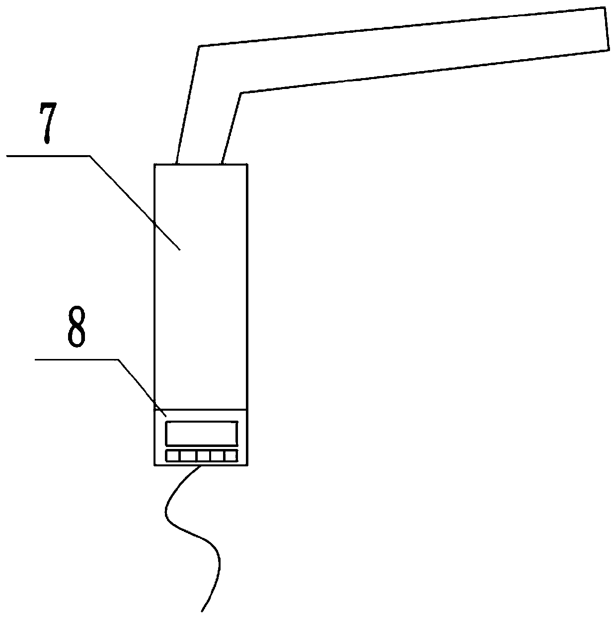
[0037] In a typical implementation of the present application, such as figure 1 , figure 2 As shown, a temperature measurement device for high-altitude equipment welding in thermal power plants is proposed.

[0038] It includes a receiving terminal 8 and a plurality of temperature measuring bodies, the temperature measuring body includes a magnetic housing 1, the magnetic housing includes an open cavity, and a power supply module 4 and a processor connected in sequence are arranged in the cavity 3 and the temperature measurement module 2, the temperature measurement module part is located outside the cavity, the magnetic shell is used to fix the temperature measurement module on the object to be measured by magnetic force, and there is a gap between the magnetic shell and the object to be measured, The processor acquires the data of the temperature measurement module and sends it to the receiving terminal for display, so as to obtain the temperature of the weldment measureme...

Embodiment 2

[0051] In another typical embodiment of the present application, a welding method assisted by the above-mentioned temperature measuring device is provided.

[0052] Include the following steps:

[0053] Adsorb several temperature measuring bodies evenly on both sides of the area to be welded;

[0054] Obtain the real-time temperature of the welding area through the temperature of the temperature measuring body during the pre-welding preheating process;

[0055] When the temperature measuring body measures that the welding area has reached the target temperature, stop preheating and weld the weld seam;

[0056] After the welding is completed, remove the multiple temperature measuring bodies located in the welding area and adsorb them on the weld to obtain the real-time temperature of the weld. When measuring the temperature of the weld, keep multiple temperature measuring bodies in the non-weld seam within the area of ​​the location;

[0057] When the temperature of the weld...


PUM


Abstract

The invention discloses a welding measuring device and a welding method. The device comprises a temperature measuring body, wherein the temperature measuring body comprises a magnetic shell, the magnetic shell comprises a cavity with an opening, a power supplying module, a processor and a temperature measuring module which are electrically connected in sequence are arranged in the cavity, the temperature measuring module is partially located outside the cavity, the magnetic shell is used for fixing the temperature measuring module on a to-be-measured object through magnetic force, and a gap isreserved between the magnetic shell and the to-be-measured object. According to the device and the method, the magnetic force is taken as the connecting fastening force to match the temperature measuring body to a pipeline of ferromagnetic material so as to obtain temperature information, so that the problem that a traditional thermocouple temperature measuring device is difficult to bundle and fix is avoided, and the position of the temperature measuring body can be changed according to the required position.

Description

technical field [0001] The present application relates to the field of welding, in particular to a welding measurement device and a welding method. Background technique [0002] With the improvement of temperature, pressure and capacity parameters of thermal power plant units, pipelines and related equipment have also begun to use high-alloy materials for multi-layer welding to ensure the strength of the welding. In order to prevent hardened structures and reduce welding stress and deformation, usually Use pre-weld preheating to reduce the cooling rate of the welded joint, and properly heat the part or the whole of the weldment according to the required pre-weld temperature. [0003] The inventors found that when controlling the heat treatment temperature, the commonly used temperature measuring devices are more inconvenient for welding related to thermal power plants: when using far-infrared temperature measuring devices, it is necessary to ensure a specific measurement dis...

Claims


Application Information

Patent Timeline
IPC IPC(8): B23K37/00G01K7/02G01K7/16G01K1/14
CPCB23K37/00G01K7/02G01K7/16G01K1/14
Inventor 陈瑞庞继勇王登第徐琨陈丽刚杨杰
Owner POWERCHINA SEPCO1 ELECTRIC POWER CONSTR CO LTD
Learn More