Femoral upper segment hip joint prosthesis and hip joint prosthesis using femoral upper segment hip joint prosthesis

A hip joint prosthesis and prosthesis technology, applied in the direction of prosthesis, femur, joint implants, etc., can solve osteoporosis and long-term prosthesis failure, mechanically stimulated bone loss, poor bone ingrowth effect, etc. Problems, achieve the effect of promoting rapid fusion and fixation, reducing bone loss, and reducing discomfort

Pending Publication Date: 2020-01-14
BEIJING CHUNLIZHENGDA MEDICAL INSTR
View PDF0 Cites 1 Cited by
  • Summary
  • Abstract
  • Description
  • Claims
  • Application Information

AI Technical Summary

Problems solved by technology

[0003] However, for the tumor-type hip prosthesis in the prior art, the upper femoral hip prosthesis is usually made into a solid metal structure, which increases the stiffness of the prosthesis itself and is prone to stress shielding, that is, due to the stiffness of the prosthesis Far greater than the stiffness of bone tissue, the bone tissue is at a low stress level for a long time, so that the bone tissue can easily cause the loss of healthy bone mass due to insufficient mechanical stimulation, thus easily causing bone mass loss. The problem of looseness and long-term prosthesis failure, and the weight of the prosthesis with a full solid structure is relatively heavy, and patients are prone to some discomfort when using it
In addition, the bone ingrowth effect on the surface of the upper femur hip joint prosthesis in the prior art is poor, which makes the stability of the prosthesis poor after implantation, and even the prosthesis itself will produce shedding, which will cause harm to the human body. infection hazard

Method used


Image

  • Femoral upper segment hip joint prosthesis and hip joint prosthesis using femoral upper segment hip joint prosthesis
  • Femoral upper segment hip joint prosthesis and hip joint prosthesis using femoral upper segment hip joint prosthesis
  • Femoral upper segment hip joint prosthesis and hip joint prosthesis using femoral upper segment hip joint prosthesis

Examples


Embodiment Construction

[0028] In order to better understand the purpose, structure and function of the present invention, an upper femoral hip joint prosthesis of the present invention will be further described in detail below in conjunction with the accompanying drawings.

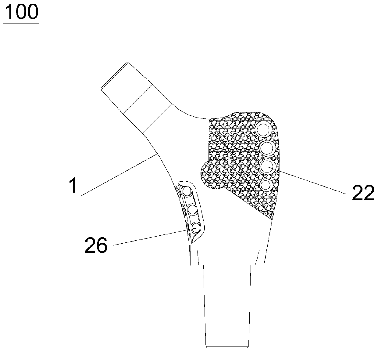
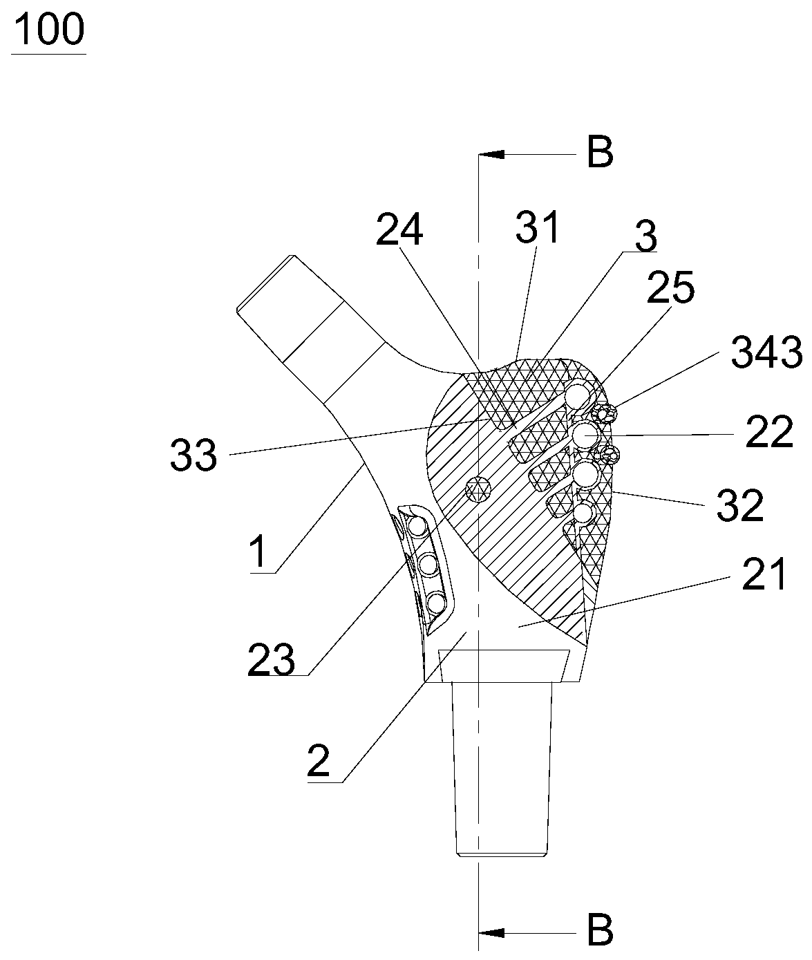
[0029] Figure 1 to Figure 4 The structure of the upper femoral hip joint prosthesis 100 according to the embodiment of the present invention is shown. like Figure 1 to Figure 4 As shown, the upper femur hip joint prosthesis 100 includes: a prosthesis body 1, combined with image 3 As shown, the prosthesis body 1 includes a load-bearing supporting prosthesis 2 close to the lesser trochanter side of the human femoral neck and an auxiliary supporting prosthesis 3 connected to the force-bearing supporting prosthesis 2 and close to the greater trochanter side of the human femoral neck. The support prosthesis 2 includes a solid prosthesis part 21 and a plurality of first suture holes 22 connected to the solid prosthesis part 21 an...


PUM


Abstract

The present invention belongs to the technical field of medical prostheses and discloses a femoral upper segment hip joint prosthesis and a hip joint prosthesis using the femoral upper segment hip joint prosthesis. The femoral upper segment hip joint prosthesis comprises a prosthesis body, the prosthesis body comprises a bearing support prosthesis and an auxiliary support prosthesis, wherein the bearing support prosthesis is close to a lesser trochanter side of a human body femoral neck, the auxiliary support prosthesis is connected with the bearing support prosthesis and close to a greater trochanter side of the human body femoral neck, and the bearing support prosthesis comprises a solid prosthesis part and a plurality of first suture holes connected with the solid prosthesis part and located inside the auxiliary support prosthesis, wherein the plurality of the first suture holes are close to the greater trochanter side of the human body femoral neck, the bearing support prosthesis is of a solid structure, and the auxiliary support prosthesis is of a three-dimensional porous structure. The femoral upper segment hip joint prosthesis can improve stability after implantation.

Description

technical field [0001] The invention belongs to the technical field of medical prosthesis, in particular to an upper femur hip joint prosthesis and a hip joint prosthesis using the same. Background technique [0002] In modern medicine, hip replacement surgery is widely used clinically, mainly for patients with femoral neck fractures, osteoarthritis of the hip, rheumatoid arthritis and ankylosing spondylitis. At present, the hip joint prosthesis is divided into many types, one of which is the tumor-type hip joint prosthesis, which can effectively improve the fixation effect after implantation because of the structures such as chute, beam and suture hole. more practical. The tumor-type hip prosthesis includes the upper femoral hip prosthesis and the lower femoral hip prosthesis connected to it. The upper femoral hip joint prosthesis mainly includes the femoral head prosthesis and the osteotomy segment prosthesis connected with the femoral head prosthesis to fill the osteoto...

Claims


Application Information

Patent Timeline
Patent Type & Authority Applications(China)
IPC IPC(8): A61F2/28A61F2/30
CPCA61F2/28A61F2/30771A61F2002/2825A61F2002/30014A61F2002/30006A61F2002/30329A61F2002/30622A61F2002/30688A61F2002/30784
Inventor 史春宝许奎雪何建民荀世界解凤宝王振国
Owner BEIJING CHUNLIZHENGDA MEDICAL INSTR
Why Eureka
Try Eureka