Eureka AIR delivers breakthrough ideas for toughest innovation challenges, trusted by R&D personnel around the world.

Screw type water vapor compressor unit and working method

A technology of screw compressor and compressor unit, which is applied in the direction of elastic fluid rotary piston type/oscillating piston type pump combination, mechanical equipment, machine/engine, etc., which can solve problems such as overheating, reduce damage and improve growth The effect of pressure

Inactive Publication Date: 2020-01-10
山东钜容重工科技有限公司
View PDF6 Cites 3 Cited by
  • Summary
  • Abstract
  • Description
  • Claims
  • Application Information

AI Technical Summary

Problems solved by technology

[0003] Aiming at the deficiencies of the prior art, the present invention provides a screw type water vapor compressor unit and working method, which increases the steam pressure through the screw compressor, and at the same time, through the external circulation structure and the addition of soft water, effectively solves the problem of The problem of overheating during work, at the same time through the crude oil filter and essential oil filter in the oil circuit, effectively avoids the problem of metal debris backflow, and the thermostat can control the oil temperature of the backflow screw compressor

Method used


Image

  • Screw type water vapor compressor unit and working method
  • Screw type water vapor compressor unit and working method
  • Screw type water vapor compressor unit and working method

Examples


Embodiment Construction

[0029] The technical solutions in the embodiments of the present invention will be clearly and completely described below in conjunction with the accompanying drawings in the embodiments of the present invention. Obviously, the described embodiments are only some of the embodiments of the present invention, not all of them; based on The embodiments of the present invention and all other embodiments obtained by persons of ordinary skill in the art without making creative efforts belong to the protection scope of the present invention.

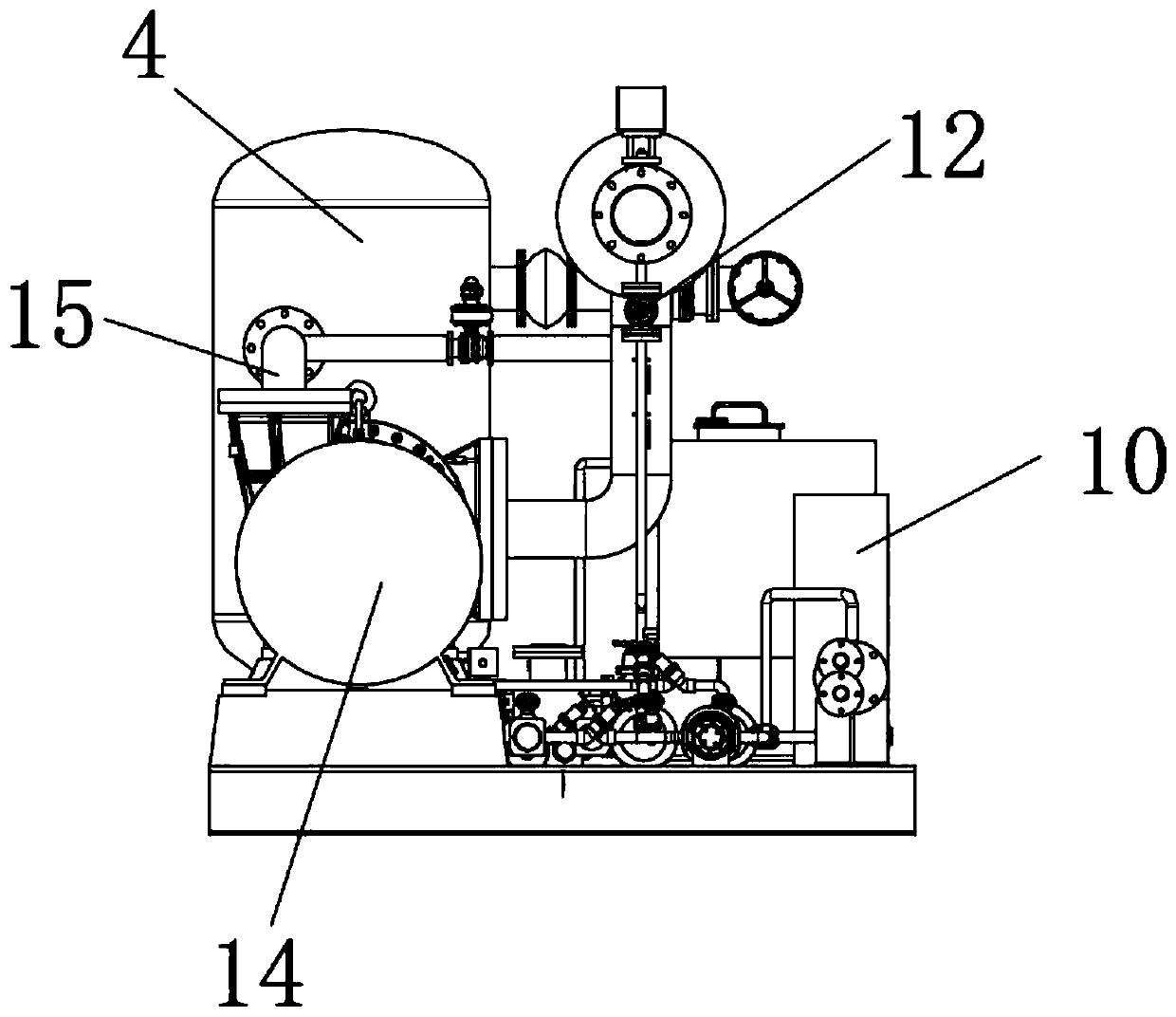
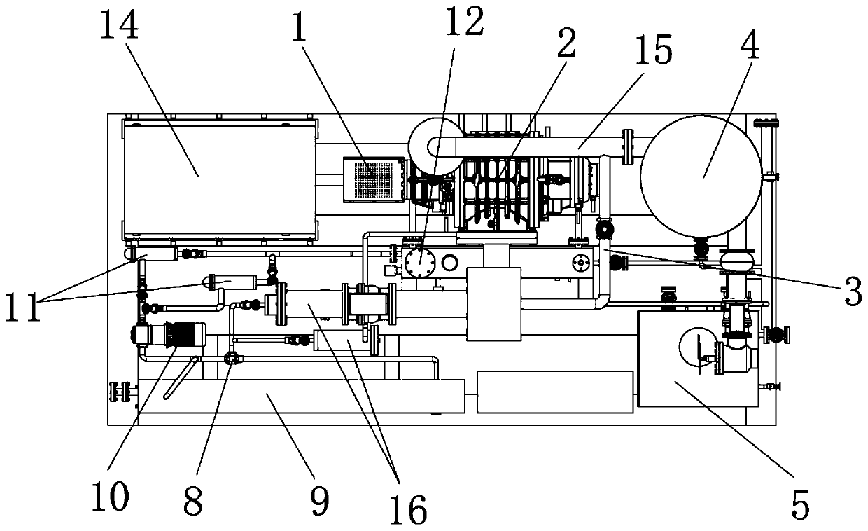
[0030] see figure 1 , figure 2 , image 3 , Figure 4 and Figure 5 As shown, a screw type steam compressor unit includes a main motor 1, a screw compressor 2, a gas-liquid separator 4, an oil tank 14, an oil cooler 9 and a soft water tank 5, and the above-mentioned structure is the main composition structure of the present invention , the output end of the main motor 1 is connected to the screw compressor 2 through a coupling, and the main...


PUM


Abstract

The invention relates to a screw type water vapor compressor unit. The screw type water vapor compressor unit comprises a main motor, a screw type compressor, a gas-liquid separator, an oil tank, an oil cooler and a softened water tank; the output end of the main motor is connected with the screw type compressor through a coupling; the gas inlet end of the screw type compressor is connected with avapor inlet pipe; the gas outlet end of the screw type compressor is connected with one end of a vapor outlet pipe; the other end of the vapor outlet pipe communicates with the gas-liquid separator;the lower end of the gas-liquid separator communicates with a main drain and an auxiliary water spraying pipeline. Compared with the original pump body pressurization manner, the screw type compressorhas the higher pressurization capability; the oil way circulation manner is adopted, so that lubricating oil in the compressor is cooled effectively, and meanwhile, the problem of reduction of lubrication efficiency due to the excessively high temperature of the lubricating oil is avoided; metal scraps carried by the lubricating oil after use are reduced by the aid of a coarse oil filter, damageto an oil pump is reduced, meanwhile, filtration is performed again by the aid of a fine oil filter, and damage to the screw type compressor is reduced.

Description

technical field [0001] The invention relates to the technical field of steam boosting, in particular to a screw-type steam compressor unit and a working method. Background technique [0002] High-pressure steam plays an important role in many industrial productions, and the existing steam boosting technology mostly uses pump boosting and works in a high-temperature and high-pressure environment at the same time, resulting in overheating of the pump body, which in turn increases the loss of the mechanical structure and shortens the The service life of the pump body is shortened. At the same time, the cooling method of the existing pump body is mostly water cooling, and the lubricating oil in the pump body reduces the lubrication efficiency when the temperature rises. The lack of an external structure makes the natural cooling of the oil circuit to the oil tank unable to meet the demand. At the same time, the metal debris generated by the compressor's working wear will flow ba...

Claims


Application Information

Patent Timeline
Patent Type & Authority Applications(China)
IPC IPC(8): F04C23/02F04C29/02F04C29/04
CPCF04C23/02F04C29/02F04C29/04F04C2210/1077
Inventor 童建云张立江尤建
Owner 山东钜容重工科技有限公司
Why Eureka
Eureka Blog
Learn More