Door plate gluing device

A door panel and gluing technology, which is applied in the field of gluing machines, can solve the problems of uneven, time-consuming and laborious gluing, etc., and achieve the effect of speeding up the production rhythm, reducing the number of gluing times, and replenishing in time

Inactive Publication Date: 2020-01-07
重庆市佳禾家具制造有限公司
View PDF10 Cites 0 Cited by
  • Summary
  • Abstract
  • Description
  • Claims
  • Application Information

AI Technical Summary

Problems solved by technology

[0004] The present invention intends to provide a door panel gluing device to solve the time-consuming and labor-intensive and uneven gluing problems of manual gluing of panels in the prior art

Method used


Image

  • Door plate gluing device
  • Door plate gluing device
  • Door plate gluing device

Examples


Embodiment 1

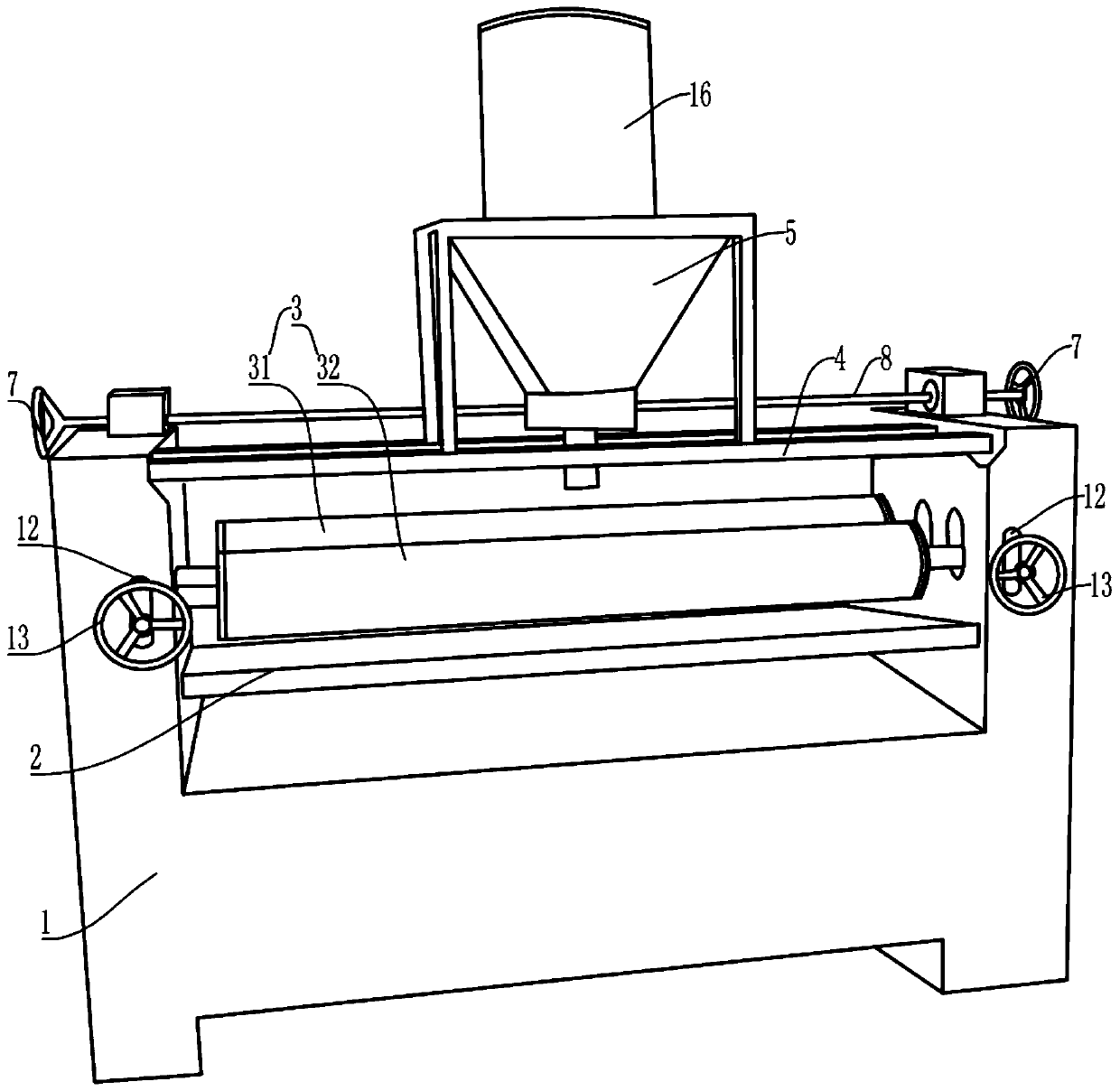
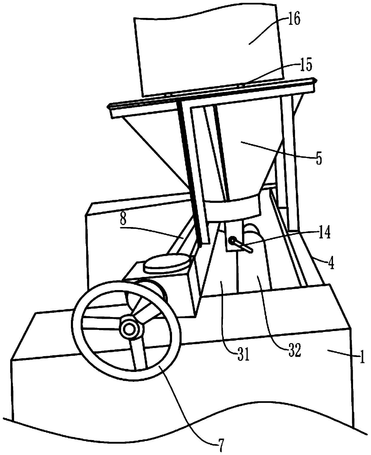
[0041] Embodiment one is basically as attached Figure 1 to Figure 4 Shown:

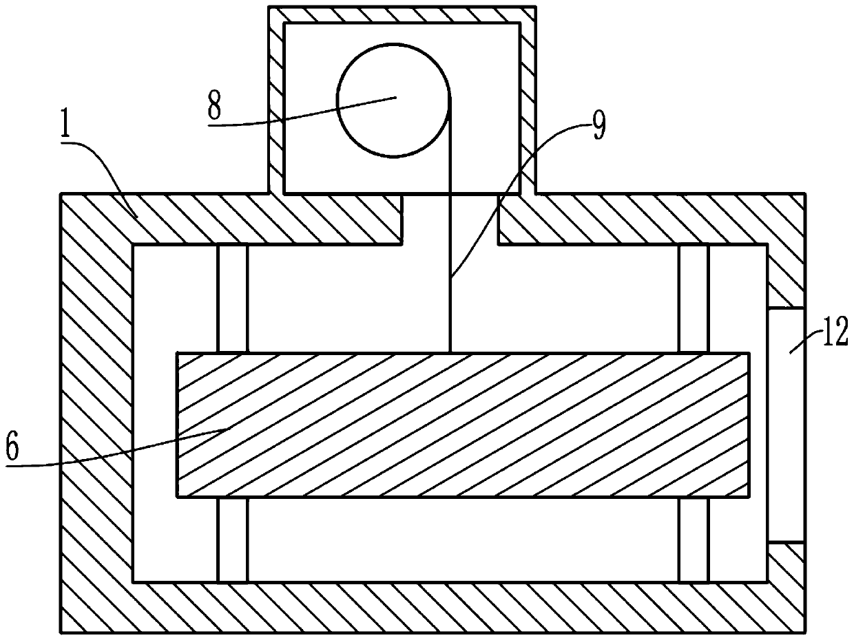
[0042] The door panel gluing device includes a frame 1, which is provided with a U-shaped through groove, and the frame 1 is installed with a platform plate 2 through screws (the platform plate 2 is located in the U-shaped channel of the frame 1) , the top of the bearing plate 2 is provided with a pair of glue rollers 3, and the bearing plate 2 is used to place plates; the top of the frame 1 is fixedly connected with a support plate 4 by bolts, and the support plate 4 is fixedly connected with a glue bucket 5 by screws (the glue hopper 5 is funnel-shaped, and the bottom of the glue barrel 16 is integrally formed with an opening), the glue pair roller 3 includes a roller one 31 and a roller two 32, and both the roller one 31 and the roller two 32 are nitrile rubber rollers.

[0043] A height adjustment unit and a width adjustment unit are installed on the left and right sides of the gluing pair rolle...

Embodiment 2

[0056] Embodiment two is basically as attached Figure 5 to Figure 8 As shown, embodiment two has carried out following improvement on the basis of embodiment one:

[0057] Also includes conveyor belt 17, lifting unit and pushing unit; Figure 7 , the conveyor belt 17 is set on the support plate 15 (the support plate 15 stretches out from the upper rubber bucket 5, and the support plate 15 is much elongated relative to the first embodiment), the rubber bucket 16 is placed on the conveyor belt 17, and the support plate 15 plays a role in the conveyor belt 17 at this time. supporting role.

[0058] combine Figure 6 , the lifting unit comprises a conveyor belt 18 and a lifting plate 19 of a chain drive, the conveyor belt 18 is fixedly connected with a connecting plate, and the lifting plate 19 is installed on the connecting plate by screws (this structure is the same as that of the chain drive in the prior art to drive the forklift to load goods). The mode that the fork moves...

Embodiment 3

[0067] combine Figure 9 , Embodiment 3 On the basis of Embodiment 2, an auxiliary lifting unit 27 is added on the right side of the conveyor belt 17. The auxiliary lifting unit 27 is different from the lifting unit on the right side in that the auxiliary lifting unit 27 does not have a lifting unit on the right side The baffle plate 26 and the ball 25 in the lifting unit are used to drop the rubber bucket 16 replaced from the conveyor belt 17 to a height that is convenient for manual removal, so as to facilitate the recovery of the replaced empty rubber bucket 16 by workers.


PUM


Abstract

The invention relates to the technical field of gluing machines, and particularly discloses a door plate gluing device. The door plate gluing device comprises a frame, a height adjusting unit and width adjusting units, wherein a bearing plate is arranged on the frame; a gluing pair roller is arranged above the bearing plate; a supporting plate is arranged on the frame; a gluing hopper is fixedly connected onto the supporting plate; the height adjusting unit and the width adjusting units are arranged on two sides of the gluing pair roller; two first sliding blocks are vertically and slidably connected onto the frame; the height adjusting unit drives the first sliding blocks to move up and down; each first sliding block is provided with one width adjusting unit; each width adjusting unit comprises a sliding rod and a second sliding block; the second sliding blocks are slidably connected to the sliding rods; the gluing pair roller comprises a first roller and a second roller; one end of the first roller is rotatably connected to one of the second sliding blocks; the other end of the first roller is slidably connected to one of the first sliding blocks; one end of the second roller isrotatably connected to the other second sliding block; and the other end of the second roller is slidably connected to the other first sliding block. According to the scheme of the door plate gluing device, the problems in the prior art that manual gluing of plates requires much time and effort, and is uneven are solved.

Description

technical field [0001] The invention relates to the technical field of gluing machines, in particular to a gluing device on a door panel. Background technique [0002] With the improvement of people's living standards, more and more door panels are used for decoration. In order to make the door panels have different patterns, it is generally necessary to cover the outer layer of the wooden structure with a patterned skin. In order to ensure that the skin can be attached to the On the board, it is necessary to brush the board with glue so that the outer skin can fit better on the board. [0003] However, in the prior art, due to the wide and long size of the boards, manual gluing of the boards is time-consuming and labor-intensive, and uneven skin bonding often occurs due to uneven gluing. Contents of the invention [0004] The present invention intends to provide a door panel gluing device to solve the problems of time-consuming and labor-intensive and uneven gluing exist...

Claims


Application Information

Patent Timeline
Patent Type & Authority Applications(China)
IPC IPC(8): B27M3/18B27G11/00
CPCB27G11/00B27M3/18
Inventor 唐静
Owner 重庆市佳禾家具制造有限公司
Why Eureka
Try Eureka