
Industrial chemical mechanical grinding equipment

A chemical mechanical and industrial technology, applied in the field of industrial chemical mechanical grinding equipment, can solve the problems of surface roughness reduction, time-consuming and labor-intensive, micropore volume reduction, etc., and achieve the effect of reducing branch recombination

Inactive Publication Date: 2019-12-31
黄功钢
View PDF6 Cites 1 Cited by
  • Summary
  • Abstract
  • Description
  • Claims
  • Application Information

AI Technical Summary

Problems solved by technology

In the chemical mechanical polishing process, the polishing pad has the functions of storing, transporting the polishing liquid, removing processing residues, transmitting mechanical loads and maintaining the polishing halo. As the chemical mechanical polishing process continues, the physical and chemical properties of the polishing pad change. , manifested as residual substances on the surface of the polishing pad, the volume of micropores is reduced, the number is reduced, the surface roughness is reduced, the branching and reorganization of the surface occurs, and a certain thickness of glaze layer is formed, resulting in the reduction of polishing efficiency and polishing quality, and then it is repaired later A glazed layer with a certain thickness is quite time-consuming and labor-intensive

Method used


Image

  • Industrial chemical mechanical grinding equipment
  • Industrial chemical mechanical grinding equipment
  • Industrial chemical mechanical grinding equipment

Examples


Embodiment

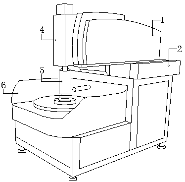
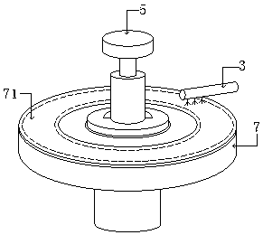
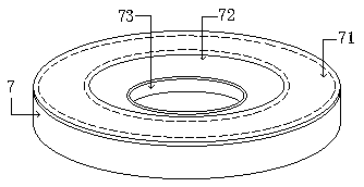
[0027] like Figure 1-Figure 8 As shown, the present invention provides a kind of industrial chemical mechanical grinding equipment, and its structure comprises machine head 1, cabinet 2, abrasive nozzle 3, driving shaft 4, grinding head mechanism 5, shield 6, turntable 7, and described turntable 7 is provided with There is a polishing pad 71, the head 1 is electrically connected to the chassis 2, the upper end of the chassis 2 is fixed with a shield 6, the shield 6 is provided with a turntable 7, and the drive shaft 4 passes through the nose 1 control, the bottom end of the drive shaft 4 is connected to the grinding head mechanism 5, one end of the abrasive spray head 3 penetrates the shield 6 and is connected to the chassis 2, and the other end corresponds to the polishing pad 71, and the turntable 7 also includes an inner chute 72 and the CIMC port 73, the inner chute 72 and the polishing pad 71 are integrated, the polishing pad 71 and the CIMC port 73 are an axis, and the ...


PUM


Abstract

The invention discloses industrial chemical mechanical grinding equipment which structurally comprises a handpiece, a case, an abrasive spray head, a drive shaft, a grinding head mechanism, a protective cover and a rotary table; the rotary table is provided with a polishing pad; electrical connection is employed between the handpiece and the case; the upper end of the case is fixedly provided withthe protective cover; the protective cover is provided with the rotary table; the drive shaft is controlled by the handpiece; the bottom end of the drive shaft is connected with the grinding head mechanism; one end of the abrasive spray head penetrates through the protective cover and is connected to the case, and the other end corresponds to the polishing pad; the abrasive spray head is added onthe outer side of the polishing pad; the inner side of the polishing pad, an inner chute and a center collection hole perform common action, and an abrasive can be embedded into the polishing pad inthe grinding process and slides downwards into the center collection hole along the slanting surface of the bowl-shaped inner chute; and in the polishing process, the old abrasive is automatically separated from the polishing surface by friction between the polishing pad and a wafer to enable a new abrasive to be exposed, so that the timely replacement phenomenon of the new and old abrasives is realized, branch reconstruction of the surface of a polishing disc is reduced, and a thick glaze layer is prevented from being formed on the surface.

Description

technical field [0001] The invention relates to the field of industrial chemical machinery, in particular, it is an industrial chemical mechanical grinding equipment. Background technique [0002] Industrial chemical mechanical polishing, also known as chemical mechanical polishing, is a combined technology of mechanical grinding and chemical corrosion. Polishes an extremely thin layer of material on the surface of a media for ultra-precise flat surface machining. In the chemical mechanical polishing process, the polishing pad has the functions of storing, transporting the polishing liquid, removing processing residues, transmitting mechanical loads and maintaining the polishing halo. As the chemical mechanical polishing process continues, the physical and chemical properties of the polishing pad change. , manifested as residual substances on the surface of the polishing pad, the volume of micropores is reduced, the number is reduced, the surface roughness is reduced, the b...

Claims


Application Information

Patent Timeline
IPC IPC(8): B24B37/00B24B37/27B24B41/04B24B57/02B24B55/02
CPCB24B37/00B24B37/27B24B41/04B24B55/02B24B57/02
Inventor 黄功钢
Owner 黄功钢
Learn More