
A large-scale ship model resistance test system in actual sea area

A resistance test and large-scale technology, which is applied in the field of ship hydrodynamic experiments, can solve the problems that affect the resistance measurement accuracy, the length of the rope, and the weight, and achieve the effect of improving measurement accuracy and stability

Active Publication Date: 2020-08-18
SOUTH CHINA UNIV OF TECH
View PDF12 Cites 0 Cited by
  • Summary
  • Abstract
  • Description
  • Claims
  • Application Information

AI Technical Summary

Problems solved by technology

This scheme is basically feasible, but there are still some problems: (1) The two stay ropes at the bow and stern are respectively connected to two winches, and the resistance of the ship model can be obtained by measuring the tension difference between the two ropes.
Therefore, the measured sinking value and pitch angle are different from the target value (the measurement result when the drag force is only applied at one point at the center of gravity), and the difference in the ship's navigation attitude will further affect the measurement of the ship model resistance value
(3) Due to the long sailing distance of the ship model, the stay rope is generally very long, and the steel wire stay rope needs to have sufficient rigidity and toughness, so its weight is relatively large
Due to the effect of its own gravity, the middle part of the tight steel wire rope will inevitably sag, so that the whole pull rope is not on the same horizontal line, which will affect the resistance measurement accuracy in the horizontal direction

Method used


Image

  • A large-scale ship model resistance test system in actual sea area
  • A large-scale ship model resistance test system in actual sea area
  • A large-scale ship model resistance test system in actual sea area

Examples


Embodiment Construction

[0029] The present invention will be further described in detail below in conjunction with the embodiments and the accompanying drawings, but the embodiments of the present invention are not limited thereto.

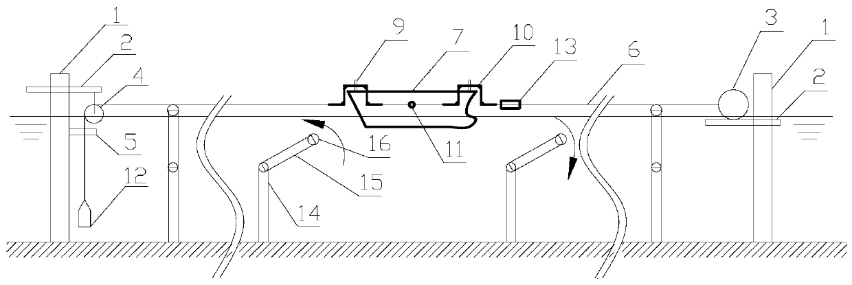
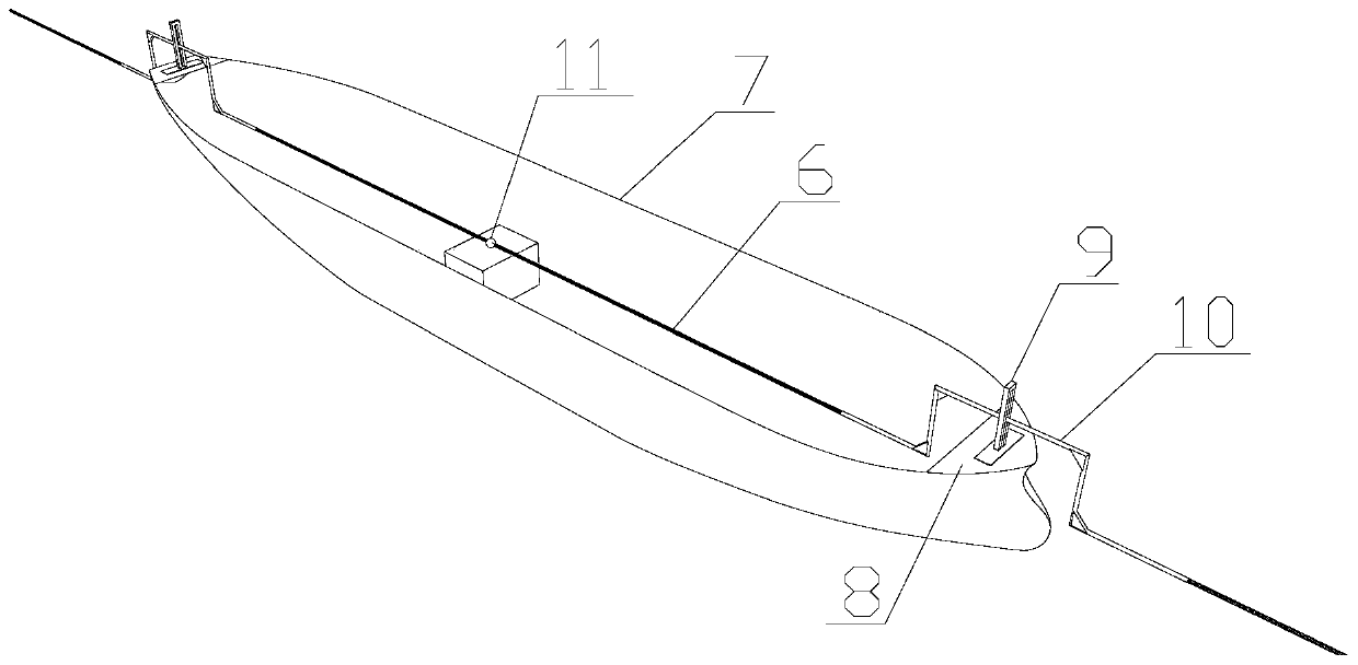
[0030] A large-scale ship model resistance test system in actual sea area includes a reference platform system, a ship model system, a tow system, a tow rope support system, and a control and measurement system.

[0031] The reference platform system includes two reference platforms fixed on the seabed. The reference platform can be a pile or a wharf fixed on the seabed. The two reference platforms are respectively fixed in the middle longitudinal plane in front of the ship model and behind the ship model. The front of the ship model refers to the direction of the bow, and the rear of the ship model refers to the direction of the stern. Both reference platforms are provided with lifting bases that can move vertically along the platform and be locked. A buoyancy material...


PUM


Abstract

The invention discloses a resistance test system for a real sea large-scale ship model. The resistance test system includes a reference platform system, a ship model system and a dragging system; thereference platform system includes two benchmark platforms fixed on a seabed; a fixed pulley and a buoyancy material removal apparatus are mounted on the benchmark platform in the rear of the ship model; the ship model system includes a fixed pull point disposed at a gravity center of the ship model, and guide rods respectively disposed on decks of a ship bow and a ship stern; the dragging systemincludes a hoist, a steel wire rope, a counterweight and a convex frame; the hoist is mounted on the benchmark platform in the front of the ship model; a middle portion of the steel wire rope is hinged and fixed with the gravity center of the ship model; one end of the steel wire rope is connected to the hoist, and the other end of the steel wire rope is across the fixed pulley to be connected tothe counterweight; and a buoyancy material covers the steel wire rope soaked in seawater. The invention provides the test system capable of accurately measuring a sailing resistance and a moving posture of the real sea large-scale ship model. The invention relates to the field of ship hydrodynamic experiments.

Description

technical field [0001] The invention relates to the field of ship hydrodynamic experiments, in particular to a large-scale ship model resistance test system in actual sea areas. Background technique [0002] A considerable part of the carbon and nitrogen oxide gases emitted globally every year comes from the exhaust emissions of ships sailing at sea. Since 2000, the International Maritime Organization (IMO) has started to study the effect of greenhouse gases, and established the Energy Efficiency Design Index (EEDI), which puts forward higher requirements for ship design, production technology, supporting equipment, and new energy technology applications. . Newly built ships of more than 400 tons that started construction after January 1, 2013 must undergo EEDI calculations and meet the corresponding energy efficiency requirements. It can be seen that new development concepts such as green ships, low-carbon economy, energy saving and emission reduction are hot topics in th...

Claims


Application Information

Patent Timeline
Patent Type & Authority Patents(China)
IPC IPC(8): G01M10/00
CPCG01M10/00
Inventor 焦甲龙黄松兴陈超核
Owner SOUTH CHINA UNIV OF TECH
Learn More