
Industrial oily fume purification equipment capable of intensively recovering waste oil

An oil fume purification and industrial technology, applied in chemical instruments and methods, dispersed particle filtration, gas treatment, etc., can solve the problems of unfavorable unified management, waste of material resources, unfavorable management and recovery of waste oil, etc., achieve good purification effect, save material resources, Good for management

Pending Publication Date: 2019-12-24
广州市绿森环保设备有限公司
View PDF0 Cites 0 Cited by
  • Summary
  • Abstract
  • Description
  • Claims
  • Application Information

AI Technical Summary

Problems solved by technology

[0002] In pharmaceutical, chemical and other enterprises, a large amount of oily fume will be produced. These oily fumes contain a large amount of harmful substances and need to be purified before being discharged into the atmosphere. Due to the large production site of the factory, multiple oil fume purification equipment are generally required for different places. Purification of industrial oil fume requires multiple oil fume purification equipment, which is a waste of material resources. Moreover, the oil fume purification equipment is located in different production sites, which is not conducive to unified management;
[0003] The existing industrial oil fume purification system needs to install multiple oil fume purification equipment in different production sites, which is a waste of material resources. Moreover, the oil fume purification equipment is located in different production sites, which is not conducive to unified management and unified recovery of waste oil

Method used


Image

  • Industrial oily fume purification equipment capable of intensively recovering waste oil
  • Industrial oily fume purification equipment capable of intensively recovering waste oil
  • Industrial oily fume purification equipment capable of intensively recovering waste oil

Examples


Embodiment 1

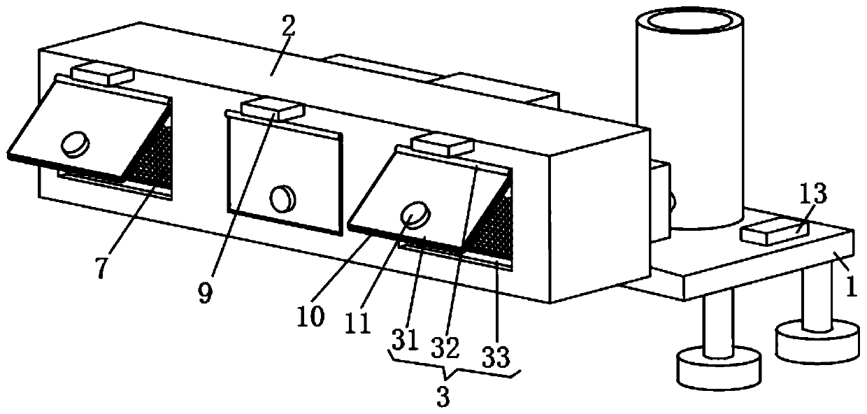
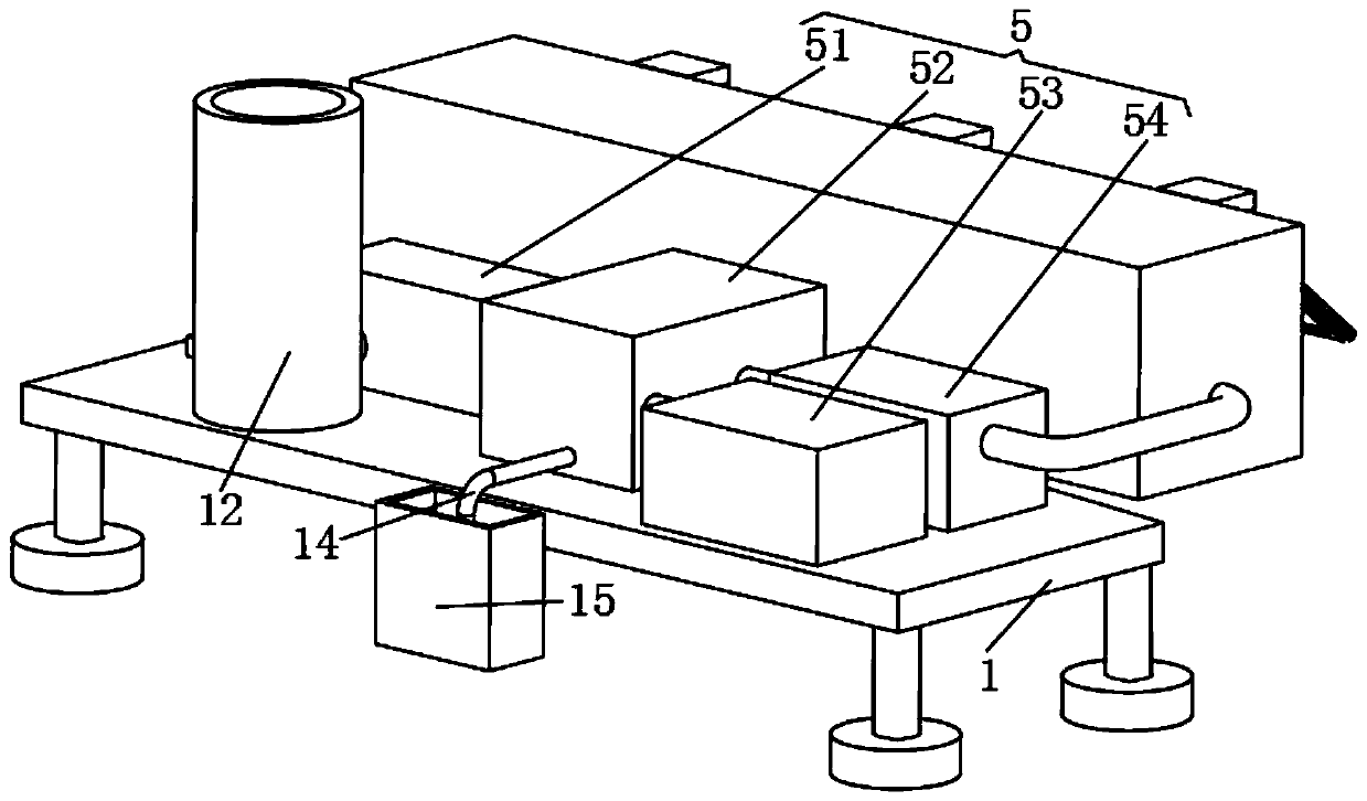
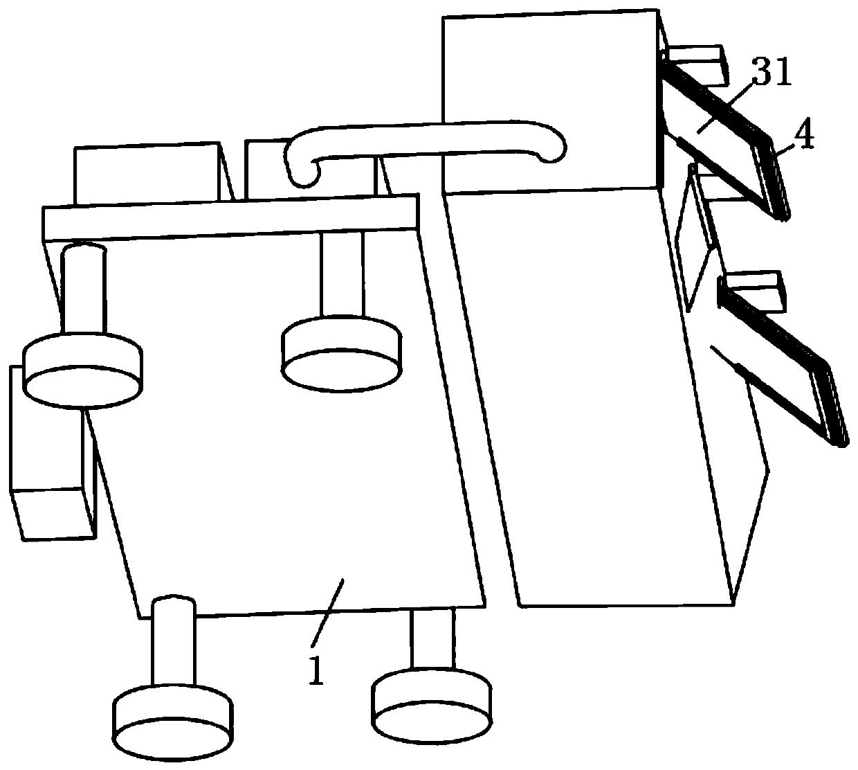
[0025] Such as figure 1 and 2 , an industrial oil fume purification equipment that can centrally recover waste oil, is characterized in that it includes a mounting plate 1, an air intake box 2, a collection unit 3 and a processing unit 5, the mounting plate 1 is a cuboid, and the four corners of the lower surface of the mounting plate 1 are uniform A bracket is provided, the lower end of the bracket is provided with a base, the air intake box 2 is a cuboid, and the front side wall of the air intake box 2 is equidistantly provided with three air intake slots, and the collection unit 3 includes a box door 31, a rotating shaft 32 and a second One electromagnet 33, described box door 31 is three, and is respectively placed in the air intake groove of air intake box 2 front side walls, and the upper end of box door 31 is connected with air intake box 2 by rotating shaft 32 rotations, and the first electromagnet There are three irons 33, and they are placed on the side wall of the ...

Embodiment 2

[0027] The difference between this embodiment and Embodiment 1 is:

[0028] In the present embodiment, there are three sieve plates 7, and they are respectively placed in three air intake slots, the sieve plate 7 is fixedly connected with the air intake box 2, and the oleophobic layer 8 is a PTFE layer, such as Figure 4 , the oleophobic layer 8 is placed on the inner side wall of the air intake box 2, the oleophobic layer 8 is fixedly connected with the air intake box 2, and there are three baffle plates 9, which are respectively placed on the front side wall of the air intake box 2 and the box door 31 In the corresponding position, the baffle plate 9 is fixedly connected with the air intake box 2 .

[0029] Specifically, the sieve plate 7 can prevent large particles of impurities from entering the air intake box 2, the oleophobic layer 8 can be used to prevent the oil in the oil fume from being adsorbed on the inner wall of the air intake box 2, and the baffle plate 9 can be...

Embodiment 3

[0031] The difference between this embodiment and Embodiment 1 is:

[0032] In this example, if figure 1 , there are three sealing rings 10, which are respectively placed on the side walls of the three box doors 31, and are fixedly connected between the sealing rings 10 and the box doors 31, such as figure 2 , the exhaust tower 12 is placed on the upper surface of the mounting plate 1, the air inlet of the exhaust tower 12 is connected to the gas outlet of the oil removal tank 52 through a connecting pipe, the waste oil tank 15 is placed on the side wall of the mounting plate 1, and one end of the oil outlet pipe 14 Placed at the lower end of the oil removal tank 52 , the oil outlet pipe 14 communicates with the inside of the oil removal tank 52 , and the other end of the oil outlet pipe 14 is placed in the waste oil tank 15 .

[0033] Specifically, the sealing ring 10 can be used to prevent air leakage at the box door 31, the exhaust tower 12 can be used to discharge the tr...


PUM


Abstract

The invention discloses industrial oily fume purification equipment capable of intensively recovering waste oil. The equipment is provided with three tank doors respectively in air inlet grooves formed in the front side wall of an air inlet tank. The upper ends of the tank doors are rotationally connected with the air inlet tank through a rotating shaft. Three first electromagnets are respectivelyin the side walls of the air inlet grooves, and are fixedly connected with the air inlet tank. The second electromagnet is arranged at the position, corresponding to the first electromagnet, of the rear side wall of the tank door. A gas outlet of a deoiling box is connected with a gas inlet of an activated carbon box; activated carbon is arranged in the activated carbon box. The emission end of the negative ion generator is connected with the air inlet of the oil removal tank through a connecting pipe, industrial oil fume in different production places can be recycled in a centralized mode, multiple oil fume purification devices do not need to be arranged in different production places, material resources are saved, and the oily fume purification equipment is located in designated placesand beneficial to management.

Description

technical field [0001] The invention relates to the technical field of oil fume purification, in particular to industrial oil fume purification equipment that can centrally recover waste oil. Background technique [0002] In pharmaceutical, chemical and other enterprises, a large amount of oily fume will be produced. These oily fumes contain a large amount of harmful substances and need to be purified before being discharged into the atmosphere. Due to the large production site of the factory, multiple oil fume purification equipment are generally required for different places. Purification of industrial oil fume requires multiple oil fume purification equipment, which is a waste of material resources. Moreover, the oil fume purification equipment is located in different production sites, which is not conducive to unified management; [0003] The existing industrial oil fume purification system needs to install multiple oil fume purification equipment in different production...

Claims


Application Information

Patent Timeline
Patent Type & Authority Applications(China)
IPC IPC(8): B01D46/10B01D46/00B01D53/32B01D53/02
CPCB01D46/10B01D46/0008B01D53/32B01D53/02B01D2259/80
Inventor 何正灏廖飞龙
Owner 广州市绿森环保设备有限公司
Learn More