
Conveying device for improving conveying efficiency of massive ore or coal

A transmission device and block technology, which is applied in the direction of conveyors, transportation and packaging, etc., can solve the problems of conveyor belts with baffle plates, potential safety hazards, and low transmission efficiency of conveyor belts

Inactive Publication Date: 2019-12-20
丰城曲江煤炭开发有限责任公司
View PDF4 Cites 2 Cited by
  • Summary
  • Abstract
  • Description
  • Claims
  • Application Information

AI Technical Summary

Problems solved by technology

[0004] The purpose of the present invention is to overcome the deficiencies of the prior art, to provide a transmission device aimed at improving the transmission efficiency of lumpy ore or coal, and to solve the problem that lumpy coal or ore is conveyed by a V-shaped conveyor belt with an included angle, and cannot be installed on the conveyor belt. The problem of the baffle plate leads to low transmission efficiency of the conveyor belt, and there are potential safety hazards

Method used


Image

  • Conveying device for improving conveying efficiency of massive ore or coal
  • Conveying device for improving conveying efficiency of massive ore or coal
  • Conveying device for improving conveying efficiency of massive ore or coal

Examples


Embodiment

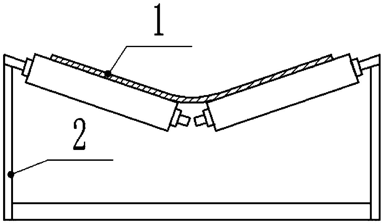
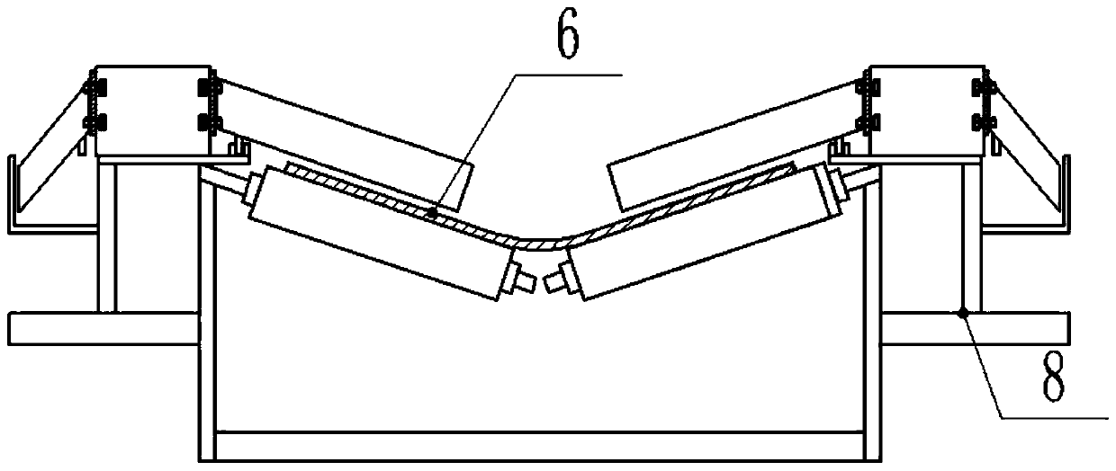
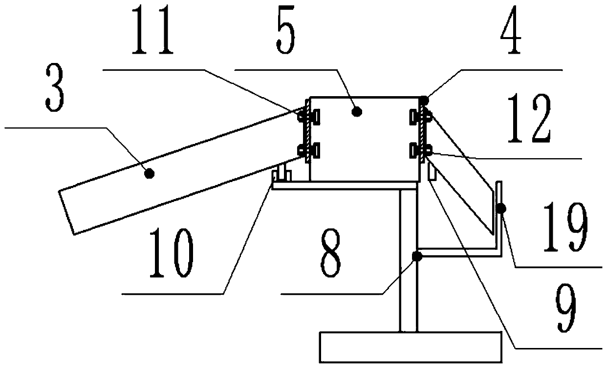
[0030] Such as Figure 1-6 As shown, the present invention is aimed at improving the conveying efficiency of lump ore or coal. The conveying device includes a conveyor belt 1, a conveyor belt V-shaped bracket 2, a baffle plate 3, a baffle plate conveyor belt 4, and a conveyor belt guide rail frame 5. The conveyor belt 1 Lay on the conveyor belt V-shaped bracket 2 to convey ore or coal in a V shape. The V-shaped conveyor belt 1 has two conveying sides 6. The conveyor belt 1 drives a circulating transmission through the power rollers 7 set at both ends of the conveyor belt V-shaped bracket 2 The conveyor belt 1 rotates, and the power roller 7 can adopt a roller and motor transmission connection structure. The motor drives the roller to rotate, and the roller is recirculated. The conveyor belt 1 and the conveyor belt V-bracket 2 are all conveyed by existing ore or coal mining Technical equipment; there are auxiliary brackets 8 on both sides of the conveyor belt V-shaped bracket 2....


PUM


Abstract

The invention discloses a conveying device for improving the conveying efficiency of massive ore or coal. The conveying device comprises a conveyor belt, a conveyor belt V-shaped bracket, stop plates,a stop plate conveyor belt and a conveyor belt guide rail bracket; the conveyor belt is laid on the conveyor belt V-shaped bracket in a V shape, and the V-shaped conveyor belt is provided with two conveying sides; and when the stop plates are ready to be taken away from the upper part of the conveyor belt by the stop plate conveyor belt, limiting columns under the stop plates can slide from a limiting slot to a V-shaped limiting slot, and then can be separated from the V-shaped limiting slot, so that the stop plates can rotate around hinge pins, and at this time, the stop plates are close tothe stop plate conveyor belt to be folded through limiting by a limiting plate, thus, the stop plates basically do not occupy the arrangement space of the conveying device, and the conveying device has the practical value. The conveying device solves the problem that when the massive coal or ore is conveyed by the V-shaped conveyor belt with an included angle, stop plates cannot be arranged on theconveyor belt, so that the conveying efficiency of the conveyor belt is low and potential safety hazards exist.

Description

Technical field [0001] The invention relates to the technical field of transmission belt equipment used in coal mines or mining plants, and in particular to a conveying device aimed at improving the conveying efficiency of lump ore or coal. Background technique [0002] In the process of coal or ore mining and transportation, the coal or ore mined is usually transported by V-shaped belt transportation. The reason why V-shaped belt transportation is used is to improve the transmission efficiency. ,Such as figure 1 As shown, in the process of conveying coal or ore by this kind of conveying device, because the conveying distance has a certain angle from the mining surface to the unloading surface, the conveyed coal or ore is in block structure, and the coal or ore in block structure is in Because of the low bite force on the V-shaped conveyor belt, it is difficult to accumulate too high, which leads to low transmission efficiency, and the phenomenon of coal or ore slipping is easy t...

Claims


Application Information

Patent Timeline
Patent Type & Authority Applications(China)
IPC IPC(8): B65G15/08B65G15/56B65G21/20
CPCB65G15/08B65G15/56B65G21/20
Inventor 李永健
Owner 丰城曲江煤炭开发有限责任公司
Learn More