Driving debugging method, behavior analysis method and driving debugging system
A debugging method and behavior analysis technology, applied in the embedded field, can solve problems such as low debugging efficiency
- Summary
- Abstract
- Description
- Claims
- Application Information
AI Technical Summary
Problems solved by technology
Method used
Image

Examples
Embodiment 1
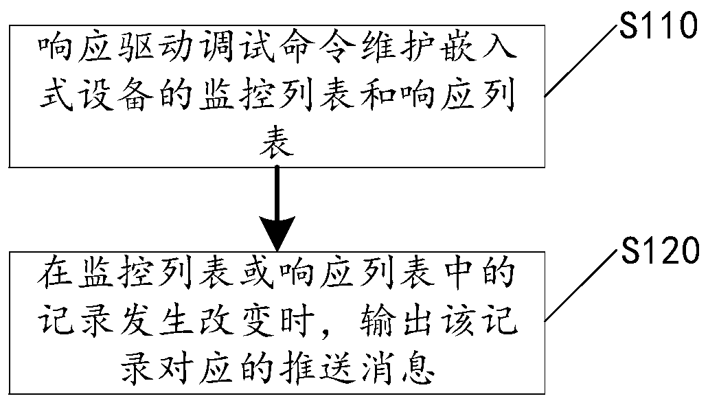
[0028] Please refer to figure 2 , the present application discloses a device-side driver debugging method, which mainly includes steps S110-S120, which will be described respectively below.
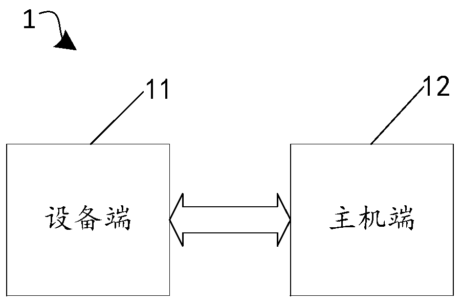
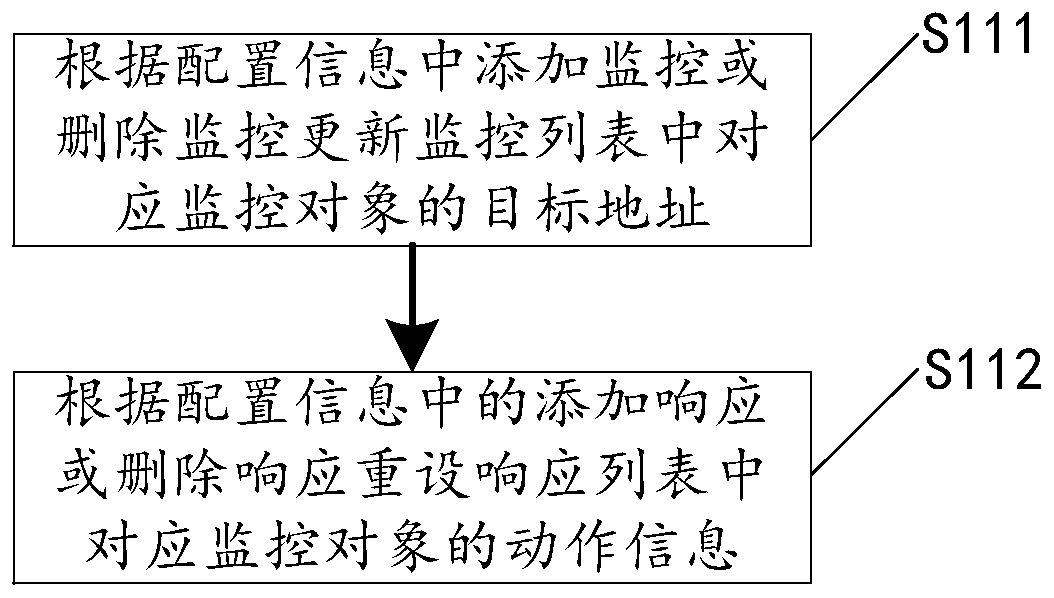
[0029] In step S110, the device end 11 responds to the driver debugging command and maintains the monitoring list and the response list of the embedded device. Among them, the driver debugging command received by the device terminal 11 includes configuration information of at least one monitoring object in the embedded device; the monitoring list here is used to record the target address of one or more monitoring objects, and the response list is used to record the address of each monitoring object. action information.
[0030] In this embodiment, the device end 11 is an embedded device, which includes one or more monitoring objects, and the monitoring objects are hardware addresses or register addresses of each hardware in the embedded device. It should be noted that an embedded devic...
Embodiment 2
[0049] Please refer to Figure 4 , on the basis of implementing the driver debugging method disclosed in No. 1, the present application also discloses a host-side behavior analysis method, the behavior analysis method includes steps S210-S220, which will be described respectively below.
[0050] In step S210, the host terminal 12 acquires a push message output by an embedded device (such as the device terminal 11). The embedded device here outputs a push message according to the driver debugging method disclosed in Embodiment 1, and the push message includes the target address and current action information of at least one monitoring object in the embedded device.
[0051] For example, when the host terminal 12 generates a driver debugging command to automatically debug the device terminal 11, or when a certain hardware in the device terminal 11 is triggered to generate a driver debugging command and perform manual driver debugging on the device terminal 11, then the The embe...
Embodiment 3
[0056] Please refer to Figure 5 , on the basis of the driver debugging method disclosed in Embodiment 1 and the behavior analysis method disclosed in Embodiment 2, the present application discloses a driver debugging system 2 for digital oscilloscopes. The driver debugging system mainly includes digital oscilloscopes 21 and customer The terminal 22 will be described separately below.
[0057] The digital oscilloscope 21 includes one or more monitoring objects, where the digital oscilloscope 21 can be regarded as an embedded device, and the monitoring objects it includes indicate hardware addresses or register addresses of various hardware inside the oscilloscope.
[0058] The client 22 establishes a communication connection with the digital oscilloscope 21 . The client 22 here is equivalent to the upper computer (or the host terminal 12 ), which can generate driver debugging commands and send them to the digital oscilloscope 21 , and can also receive push messages output by ...
PUM
 Abstract
Description
Claims
Application Information
 - R&D
- Intellectual Property
- Life Sciences
- Materials
- Tech Scout
- Unparalleled Data Quality
- Higher Quality Content
- 60% Fewer Hallucinations
Browse by: Latest US Patents, China's latest patents, Technical Efficacy Thesaurus, Application Domain, Technology Topic, Popular Technical Reports.
© 2025 PatSnap. All rights reserved.Legal|Privacy policy|Modern Slavery Act Transparency Statement|Sitemap|About US| Contact US: help@patsnap.com