Sample purification and concentration device

A concentration device and sample technology, which is applied in the direction of measurement device, test sample preparation, sampling, etc., can solve the problems of difficult processing, long filtration time, easy to break membrane, etc., and reduce the probability of concentration polarization and purity And the effect of high recovery efficiency and increased membrane filtration area

Pending Publication Date: 2019-12-10
杭州九龄科技有限公司
View PDF1 Cites 1 Cited by
  • Summary
  • Abstract
  • Description
  • Claims
  • Application Information

AI Technical Summary

Problems solved by technology

[0004] However, the conventional ultrafiltration centrifuge tubes currently available in the market have various defects. There is a certain inclination between the filter membrane and the feed liquid. The centrifugal filtration is a dead-end filtration, which is very easy to form concentration polarization. Accumulation on the surface of the membrane makes it difficult to concentrate. At the same time, it is easy to lead to long filtration time, low protein recovery rate, and the product is often easily damaged. At the same time, the products on the market are manufactured in multiple processes. The filter membrane is first fixed on the support plate. Then it is connected with the casing, which will easily cause membrane damage during the production process, the product qualification rate is low, and the price is high; therefore, it is urgent to increase the filtration speed, simplify the production process, and improve the product qualification rate to reduce production costs.
[0005] The patent notification number is CN206924902U discloses a purification and concentration device, after the filter membrane of the device is fixed on the inside of the filter plate, it is vertically or obliquely fixed on the side wall of the filter membrane support or horizontally fixed on the bottom of the filter membrane support; The membrane is fixed on the filter membrane support, and then they are welded on the trough tube, the membrane is easy to break, and the yield is low; the feed liquid of the trough tube passes through the membrane and enters the trough of the support plate, and the outlet is in the trough On the back, and it is a pinhole hole, it is very difficult to process
[0006] In the current commercially available purification and concentration devices, there is a certain inclination angle between the membrane and the feed liquid. Under the action of an external driving force, molecules larger than the membrane pore size cannot pass through the membrane pores, and are easy to accumulate in the membrane pores and block the membrane pores, resulting in slow concentration. , until the membrane pores are completely blocked, resulting in the failure of separation and concentration

Method used


Image

  • Sample purification and concentration device
  • Sample purification and concentration device
  • Sample purification and concentration device

Examples


Embodiment 1

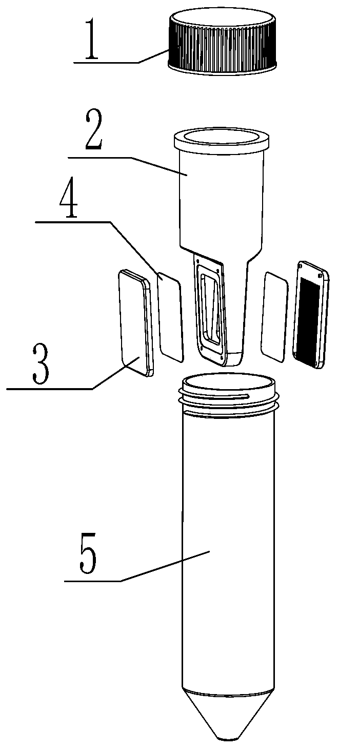
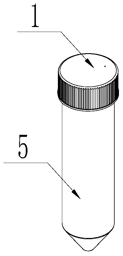
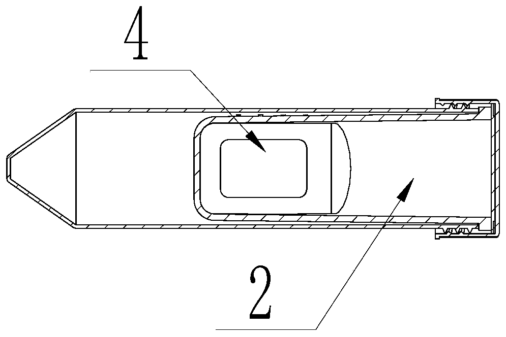
[0034] Such as Figure 1-5 As described above, the present invention provides a sample purification and concentration device, including an end cap 1, a trough tube 2, a filter membrane support 3, a filter membrane 4, and a centrifuge tube 5; the inside of the filter membrane support 3 has a feed liquid flow channel 6, The outlet 7 of the flow channel leads directly to the bottom, and the trough tube 2 has a sample holding cavity, and the side of the trough tube 1 has a liquid outlet connected to the sample holding cavity, and the filter membrane 4 is fixed on the trough tube first. 1 and cover the liquid outlet, and then the filter membrane support 3 is attached to the filter membrane 4 and fixed vertically or obliquely on the trough tube 2, and then inserted into the centrifuge tube 5 together with the trough tube 2, and then passed The end cap 1 is tightly closed, and the sample holding chamber, the filter membrane 4, the feed liquid flow channel and the centrifuge tube 5 ar...

Embodiment 2

[0054] Using the same test procedure as in Example 1, the difference is that a smaller device of the present invention is used, and the initial volume is changed to 5ml.

[0055] Table 3 Comparison test of 5ml centrifugal ultrafiltration device for the removal of sodium chloride and the recovery of protein solution

[0056]

[0057] Table 3 shows that, by comparison, it is found that the device of the present invention does not change the protein recovery rate and desalination rate with the change of the specification volume, and it also has better performance than similar commercially available products, and is also better than the performance of the patent CN206924902U applied for earlier , at the same time, the desalination rate does not depend on the concentration and volume of the sample. Desalting by ultrafiltration does not change the composition of the buffer, and repeated dilution and filtration. This process is called equal-volume ultrafiltration, which is repeated...


PUM


Abstract

The invention discloses a sample purification and concentration device which comprises an end cover, a trough pipe, a filter membrane support, a filter membrane and a centrifugal pipe, a feed liquid runner is arranged on the inner side of the filter membrane support; the runner outlet is straight to the bottom, the trough pipe is provided with a sample accommodating cavity; a liquid outlet communicated with the sample accommodating cavity is formed outside the side of the trough pipe; the filter membrane is fixed on the outer side of the trough pipe and covers the liquid outlet, the filter membrane support is vertically or obliquely fixed on the trough pipe after being tightly attached to the filter membrane, then the filter membrane support and the trough pipe are sleeved into the centrifugal pipe together, and the end cover is tightly covered, the sample containing cavity, the filter membrane, the feed liquid flow channel and the centrifugal pipe are sequentially communicated to forma purification and concentration channel. The device is used for separating, cleaning, purifying, filtering, desalting and concentrating a sample under the action of driving force or centrifugal force; in the operation process, other media are not needed, other pipetting devices are not needed in the operation process, any sample loss is avoided, and a very small number of samples can be separated, purified, concentrated and the like.

Description

technical field [0001] The invention relates to a sample purification and concentration device, which is mainly used in the field of biological products such as separation, purification, concentration and desalination. Background technique [0002] Centrifugal filtration devices are mainly used for separation, cleaning, concentration, desalination and purification of biological product samples, such as urine, diagnostic reagents, monoclonal antibodies, plasma, spinal fluid, viruses, etc., with small processing capacity and high concentration multiples , the separation of samples, the speed of filtration and purification process and the recovery of residual samples have extremely important scientific research value for scientific research. However, the currently commercially available filter centrifuge tubes have low concentration after purification and concentration, and have a large sample loss, which is difficult to meet the high requirements of clinical and laboratory, es...

Claims


Application Information

Patent Timeline
Patent Type & Authority Applications(China)
IPC IPC(8): G01N1/34G01N1/40
CPCG01N1/34G01N1/4005
Inventor 唐勇红刘锋郭爱连
Owner 杭州九龄科技有限公司
Why Eureka
Try Eureka