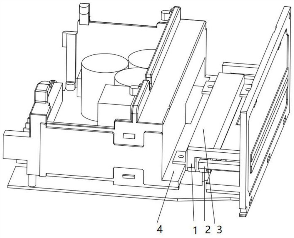
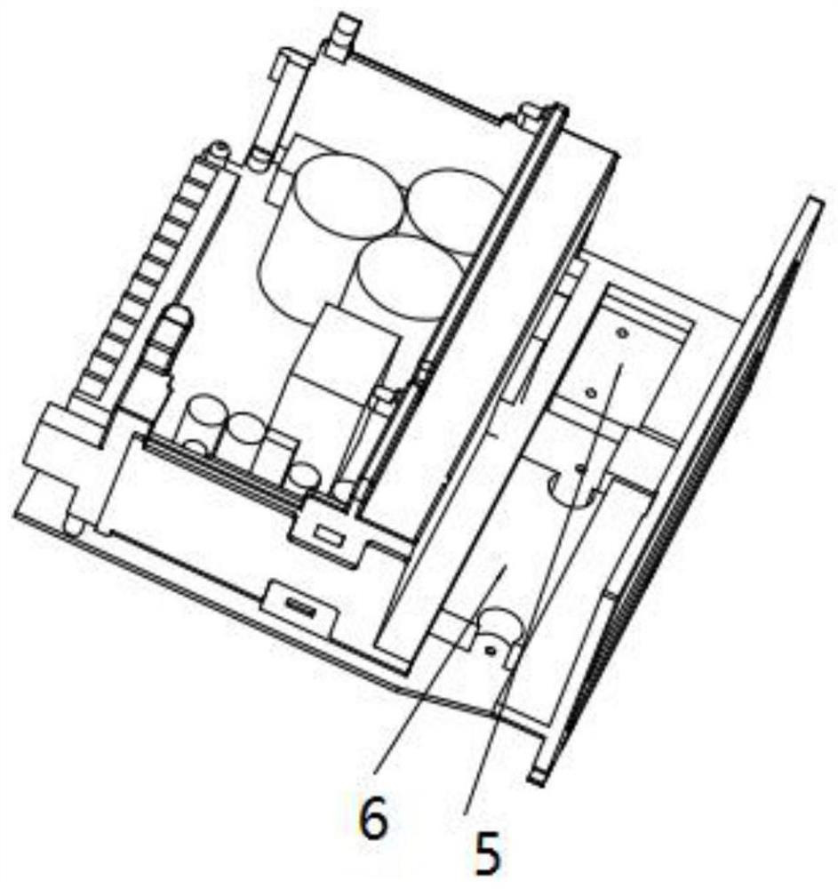
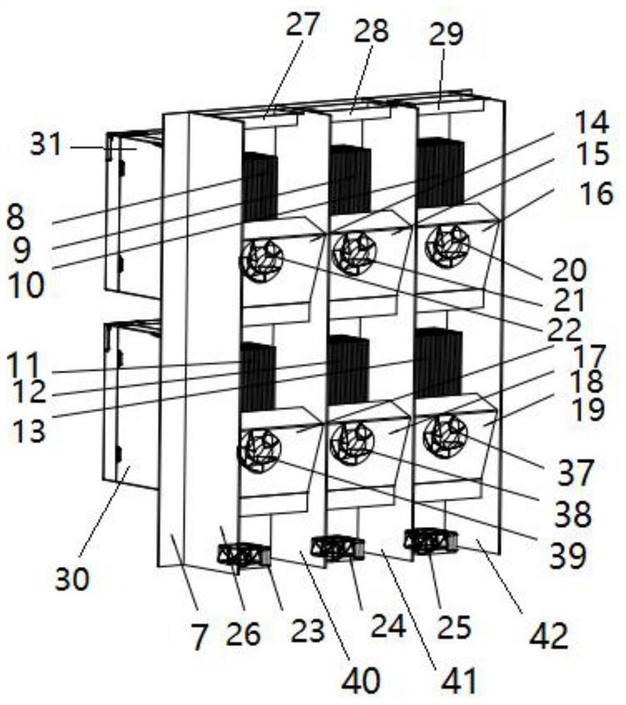
A heat dissipation structure of a servo drive and a control cabinet including the same

A technology of servo drive and heat dissipation structure, which is applied to the structural parts of electrical equipment, cooling/ventilation/heating transformation, electrical components, etc. It can solve problems such as general heat dissipation effect, compact structure of low-power models, and inability to install fans. Achieve the effects of reducing the chance of dust entering the servo drive, improving the IP protection level, and reducing the structural width

Active Publication Date: 2021-05-07
GREE ELECTRIC APPLIANCES INC
View PDF11 Cites 0 Cited by
  • Summary
  • Abstract
  • Description
  • Claims
  • Application Information

AI Technical Summary

Problems solved by technology

[0002] Existing servo drive manufacturers use the internal fan of the drive to provide the air source for heat dissipation, combined with the openings at both ends of the drive shell, the internal air duct, and the air guide column to discharge the heat from the radiator to achieve the purpose of cooling the servo drive. The cooling capacity of the heat dissipation method is limited, and the heat dissipation effect of the over-high-power components is average, and the low-power model has a compact structure and cannot be equipped with a fan. not functioning properly

Method used


Image

  • A heat dissipation structure of a servo drive and a control cabinet including the same
  • A heat dissipation structure of a servo drive and a control cabinet including the same
  • A heat dissipation structure of a servo drive and a control cabinet including the same

Examples


Embodiment Construction

[0029] In order to make the above objects, features and advantages of the present invention more comprehensible, specific implementations of the present invention will be described in detail below in conjunction with the accompanying drawings. In the following description, numerous specific details are set forth in order to provide a thorough understanding of the present invention. However, the present invention can be implemented in many other ways different from those described here, and those skilled in the art can make similar improvements without departing from the connotation of the present invention, so the present invention is not limited by the specific implementations disclosed below.

[0030] It should be noted that when an element is referred to as being “fixed” to another element, it can be directly on the other element or there can also be an intervening element. When an element is referred to as being "connected to" another element, it can be directly connected ...


PUM


Abstract

The invention relates to a heat dissipation structure of a servo drive and a control cabinet including the same. A heat dissipation air duct and a heat pipe are arranged in the cabinet of the servo drive. The evaporation section of the heat pipe contacts each heating component of the servo drive. There is a working medium inside the heat pipe, and the working medium can absorb the heat transmitted to the evaporation section and undergo a liquid-gas phase change, then flow to the condensation section and undergo a gas-liquid phase change in the condensation section, and cooperate with the air duct to discharge the heat, The setting of the heat pipe and its internal working medium can quickly take away the heat of the servo drive, and solve the heat accumulation problem of the traditional servo drive heat dissipation structure. In this way, there is no need to set fans and cooling holes inside the servo drive, which greatly reduces the size, volume and weight are effectively reduced, and is suitable for control cabinets of various power types.

Description

technical field [0001] The invention relates to the technical field of heat dissipation, in particular to a heat dissipation structure of a servo driver and a control cabinet including the same. Background technique [0002] Existing servo driver manufacturers use the internal fan of the driver to provide the air source for heat dissipation, combined with the openings at both ends of the driver's shell, the internal air duct, and the air guide column to discharge the heat from the radiator to achieve the purpose of cooling the servo driver. This air-cooled The cooling capacity of the heat dissipation method is limited, and the heat dissipation effect of the over-high-power components is average, and the low-power model has a compact structure and cannot be equipped with a fan. not functioning properly. Contents of the invention [0003] Aiming at the problems existing in the above-mentioned prior art, the present invention provides a servo drive heat dissipation structure...

Claims


Application Information

Patent Timeline
Patent Type & Authority Patents(China)
IPC IPC(8): H05K7/20
CPCH05K7/20145H05K7/20336
Inventor 崔迪谢慧皇叶俊奇宋健耿继青
Owner GREE ELECTRIC APPLIANCES INC
Why Eureka
Try Eureka