Direct-current electric field-traveling wave magnetic field composite method for improving quality of cladding layer

A technology of traveling wave magnetic field and direct current electric field, which is applied in coating, metal material coating process, etc., can solve the problems of not considering the cladding speed of laser cladding and the short existence time of molten pool, and achieve the rise and escape time of pores The effect of increasing, increasing the number of crystal nuclei, and increasing the charge amount of particles

Pending Publication Date: 2019-12-03
魏永强
View PDF0 Cites 2 Cited by
  • Summary
  • Abstract
  • Description
  • Claims
  • Application Information

AI Technical Summary

Problems solved by technology

[0007] Through the search of domestic and foreign literature, current researchers mainly focus on applying magnetic or electric fields to welding or laser cladding, but they do not take into account the unique characteristics of laser cladding, such as fast cladding speed and short existence time of molten pool.

Method used


Image

  • Direct-current electric field-traveling wave magnetic field composite method for improving quality of cladding layer
  • Direct-current electric field-traveling wave magnetic field composite method for improving quality of cladding layer
  • Direct-current electric field-traveling wave magnetic field composite method for improving quality of cladding layer

Examples


Embodiment 1

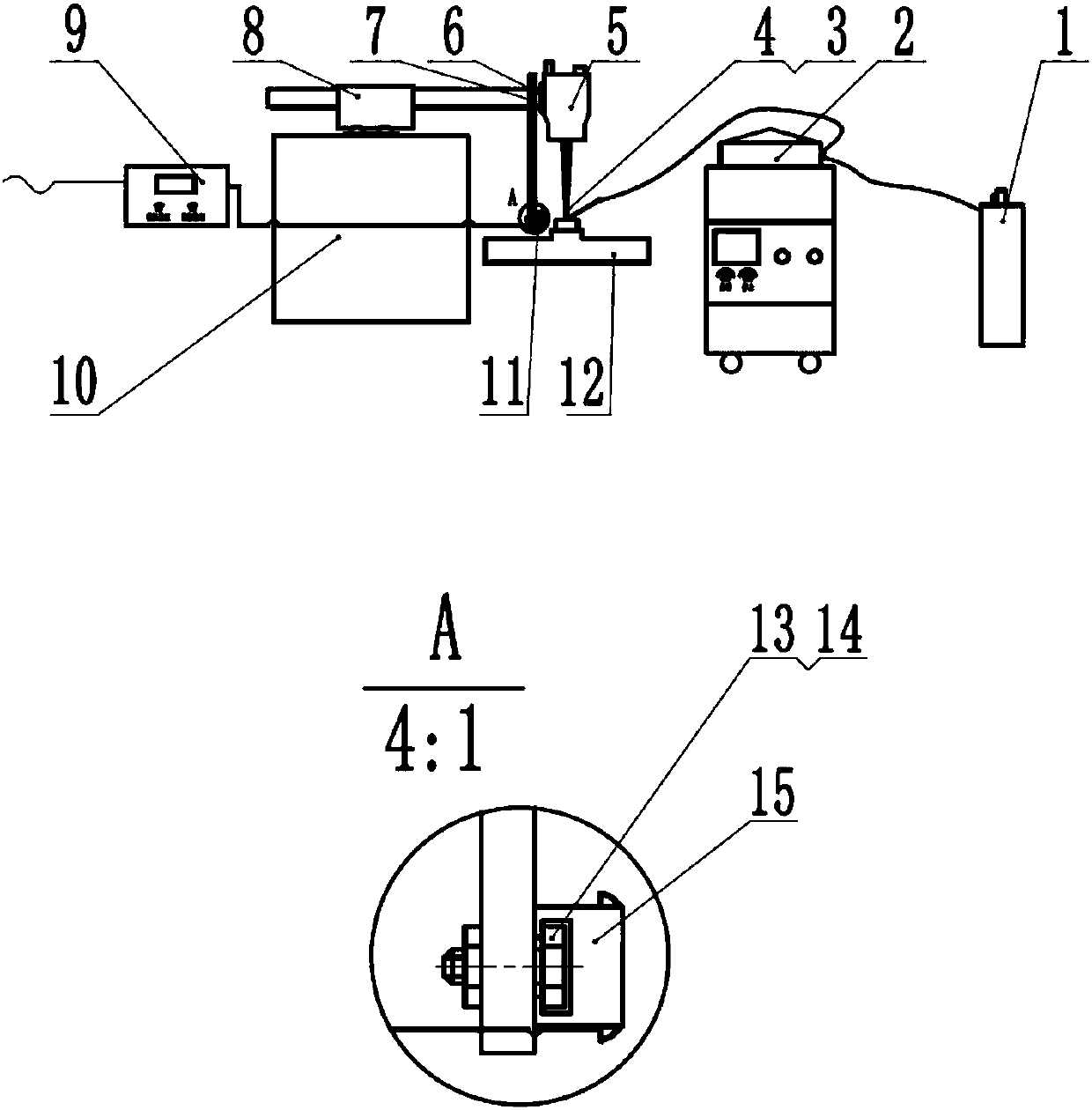
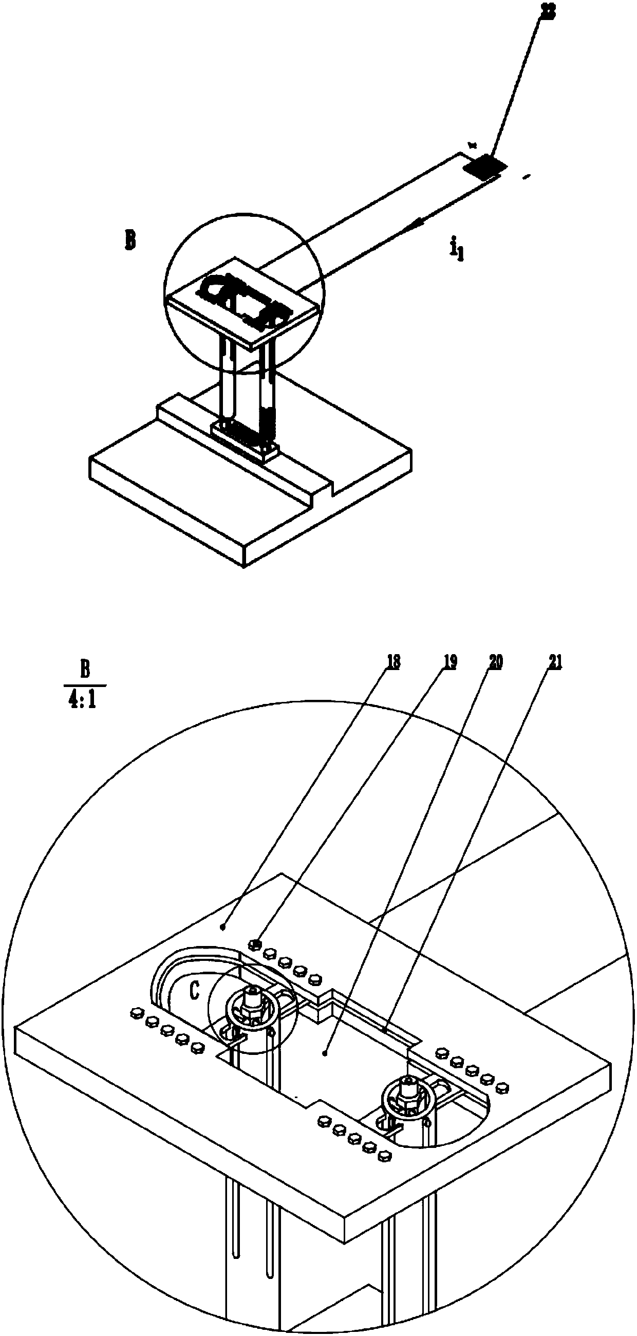
[0028] 1. Fix Q235 (chemical composition percentage Wt%: 0.5Mn, 0.3Si, 0.2C, 0.05S, 0.045P, Fe balance) substrate plate with a size of 100mm*20mm*20mm (length*width*height) Place it on the workbench, fine-tune the relative position of the electrode substrate and the numerical control device, so that the focus of the laser beam is located at the center of the rectangular through hole. Adjust the position of the connecting lug so that the distance between the two electrode rollers is d 1 25mm, adjust the position of the fastening nut on the electrode column, so that the electrode roller is pressed against the upper surface of the substrate;

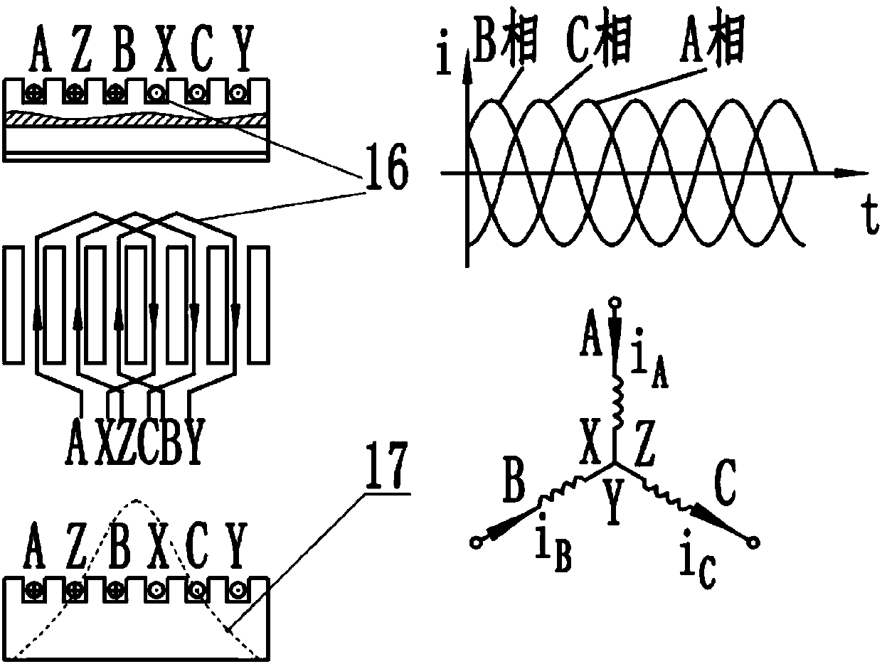
[0029] 2. Turn on the power switch of the DC electric field to make the current i through the workpiece 1 is 5kA, after the output current of the DC electric field device is stable, turn on the traveling wave magnetic field power supply control device, so that the energizing frequency of each phase of the traveling wave magnetic field is 5...

Embodiment 2

[0032] Method is all identical with embodiment 1, only embodiment 1 the 1st walking wave magnetic field power source control device makes each phase energization frequency be 80Hz, each phase energization current i A (or i B i C ) for 3A.

Embodiment 3

[0034] The methods are all the same as in Example 1, only the second step of Example 1 passes the workpiece current i 1 is 8kA, the traveling wave magnetic field power supply control device makes the frequency of each phase energized at 80Hz, and the energized current of each phase i A (or i B i C ) for 3A.


PUM


Abstract

The invention discloses a direct-current electric field-traveling wave magnetic field composite method for improving the quality of a cladding layer. The devices adopted by the method mainly comprisea laser cladding numerical control device, a traveling wave magnetic field device and a direct-current electric field device. According to the composite device, firstly, the direct-current power supply device is started before cladding until the cladding is completed, and secondly, a traveling wave magnetic field is applied to a molten pool during the cladding process, so that the charged quantityof non-magnetic particles and particles with less charges in the molten pool is increased under the action of impressed current. Furthermore, in an external follow-up traveling wave magnetic field, the Lorentz force borne by the liquid metal particles is remarkably enhanced, the stirring effect on a molten pool is enhanced, the effects of fluid scouring, crushing and the like on the dendrites areincreased, the grain size is reduced, the fine grain strengthening effect is obvious, the structure defects of a cladding layer are reduced, and the quality is improved. The composite device effectively solves the problems that the non-magnetic and charged particles are subjected to small Lorentz force in an electromagnetic field, and the electromagnetic stirring effect of the magnetic field on the molten pool is small.

Description

technical field [0001] The invention is a composite device that enhances the strong stirring effect of the traveling wave magnetic field on the molten pool by applying a large current to the liquid molten pool, which can greatly improve the cladding quality and reduce the occurrence of cladding layer defects (such as pores, inclusions, cracks, etc.) , belonging to the field of material surface modification. Background technique [0002] Laser cladding technology and 3D printing technology are new technologies that have developed rapidly in industry in recent years. What both have in common is that they use a high-density laser beam to irradiate the powder near the focus of the laser beam for a short time to partially melt it and the upper surface of the substrate and cool it rapidly, which can be obtained on a substrate with good plasticity and toughness. Alloy cladding layer with high strength, hardness and excellent wear resistance. Since the physical and chemical parame...

Claims


Application Information

Patent Timeline
Patent Type & Authority Applications(China)
IPC IPC(8): C23C24/10
CPCC23C24/10
Inventor 王好平魏永强李慧娟侯军兴刘源张华阳蒋志强
Owner 魏永强
Why Eureka
Try Eureka