
Toner and image forming method

a technology of toner and image, applied in the field of toner, can solve the problems of lowering the charge quantity, unable to obtain stable images, and line marks (development line marks), and achieve the effects of stable image density stability and image quality

Active Publication Date: 2010-04-27
CANON KK
View PDF11 Cites 16 Cited by
  • Summary
  • Abstract
  • Description
  • Claims
  • Application Information

AI Technical Summary

Benefits of technology

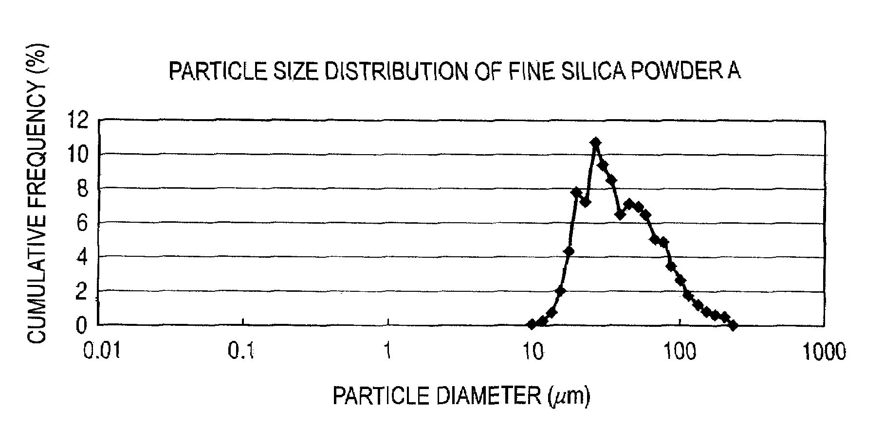
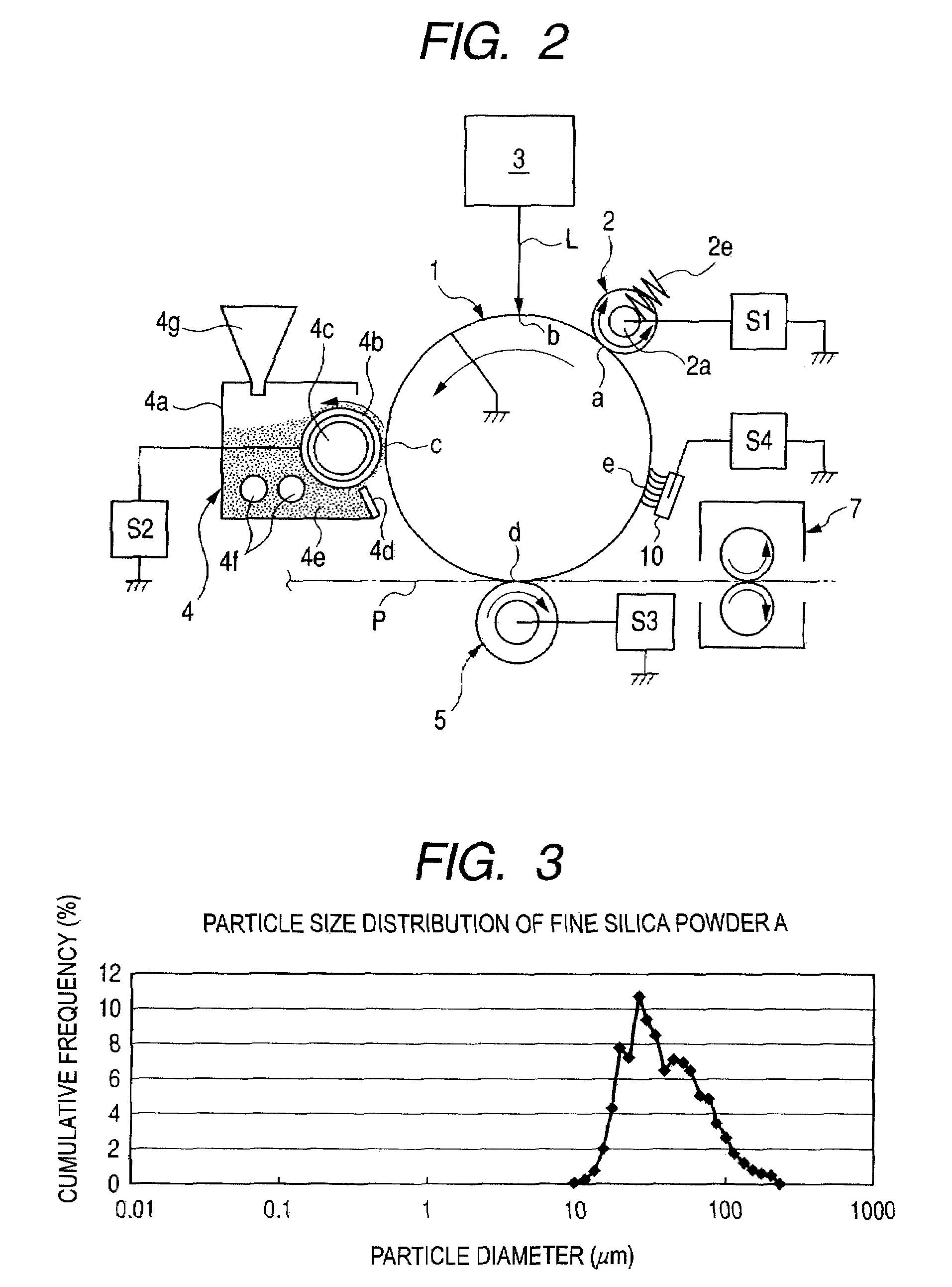
The present invention provides a toner and image forming method that can resolve issues such as fogging, poor running stability, and melt-sticking of toner and fine silica powder in long-term service. The toner comprises toner particles and fine silica powder that have been surface-treated with dimethylsilicone oil and have an appropriate particle size distribution. The fine silica powder is kept from coming liberated from the toner or buried in toner particles, resulting in stable image density and quality over a long period of time. The toner and fine silica powder can also be maintained in stable fluidity and chargeability, ensuring good transfer performance and running stability.

Problems solved by technology

As the result, any toner layer disorder due to the matter having thus melt-stuck thereto may appear on images to tend to cause line marks (development line marks) on the images.
As the result, such matter having melt-stuck thereto tends to cause a lowering of charge-providing ability of the carrier to the toner, so that in some cases the charge quantity of toner can not stabilize to make image density unstable or cause fog seriously and make it unable to obtain stable images over a long period of time.
These hydrophobic fine silica powders are those having been treated with dimethyldichlorosilane or hexamethyldisilazane, and can not be said to be sufficiently hydrophobic, thus, in a severe high-temperature and high-humidity environment, these may cause a lowering of charge quantity because of moisture absorption.
As the result, a problem tends to come about such that, as a result of long-term service, image density becomes unstable or fog occurs seriously.
As the result, the toner may have a poor fluidity to tend to cause fog.
However, such a powder subjected to disintegration treatment has a portion remaining untreated, and hence, though it is temporarily made fine, has a problem that it may again agglomerate with lapse of time.
As the result, in long-term service, the fine silica powder tends to come liberated from toner, where the fine silica powder having come liberated therefrom tends to adhere or melt-stick to the toner carrying member and control member in the case of the one-component developing system, or to carrier particles in the case of the two-component developing system, tending to cause difficulties in images.
However, where the powder subjected to disintegration treatment in this way is mixed in the toner by external addition, the fine silica powder tends to come buried in toner particles during long-term service because the agglomerates have been too finely disintegrated.
As the result, as a toner, it tends to become greatly low in fluidity to become poor in transfer performance, or the charge quantity of toner tends not to stabilize to make image density unstable or cause fog seriously.
Thus, it has been difficult to make the charge quantity of toner stabilize in every environment and also to keep the toner and / or the fine silica powder from melt-sticking to the toner carrying member and control member or to the carrier particles.

Method used


Image

  • Toner and image forming method
  • Toner and image forming method
  • Toner and image forming method

Examples


example 1

[0220]An aqueous dispersion medium and a polymerizable monomer composition were each prepared in the following way.

[0221]Preparation of Aqueous Dispersion Medium:

[0222]In 292 parts by mass of ion-exchanged water, 47 parts by mass of an aqueous 0.1 mol / liter Na3PO4 solution was introduced, followed by heating to 60° C. and thereafter stirring at 13,000 rpm by using a TK-type homomixer (manufactured by Tokushu Kika Kogyo Co., Ltd.). To the resultant mixture, 68.5 parts by mass of an aqueous 1.0 mol / liter CaCl2 solution was slowly added to obtain an aqueous medium of pH 6 containing a calcium phosphate compound.

[0223]Preparation of Polymerizable Monomer Composition:

[0224]

Styrene83parts by massn-Butyl acrylate17parts by massColorant (C.I. Pigment Blue 15:3)5parts by massCharge control agent1part by mass(3,5-di-t-butylsalicylic acid metal compound)Saturated polyester resin obtained by4parts by masscondensation polymerization of propylene oxideand ethylene oxide addition products of bisph...

examples 2 to 4

[0241]Toners 2 to 4 were obtained in the same manner as in Example 1 except that the fine silica powder was changed for the fine silica powders B to D, respectively. Evaluation was also made in the same way as in Example 1 to obtain the results shown in Table 3.

examples 5 to 7

[0243]Toners 6 to 8 were obtained in the same manner as in Example 1 except that the fine silica powder was changed for the fine silica powders F to H, respectively. Evaluation was also made in the same way as in Example 1 to obtain the results shown in Table 3.


PUM

PropertyMeasurementUnit
weight average particle diameteraaaaaaaaaa
laser diffraction particle size distribution meteraaaaaaaaaa
BET specific surface areaaaaaaaaaaa

Abstract

A toner is provided which has toner particles and a fine silica powder mixed by external addition to the toner particles. The toner has a weight average particle diameter of 4.0 to 9.0 μm. The fine silica powder is subjected to hydrophobic treatment with dimethylsilicone oil, and has, in particle size distribution based on volume, a peak at which cumulative frequency is largest, in the measurement range of 0.02 μm to 1,000.00 μm; the cumulative frequency of 0.10 μm to less than 1.00 μm being 7.0% or less, and, the fine silica powder fulfills the following conditions:1) A+B≧93.0;2) 0.45≦A / B≦6.00; and3) the value of [(carbon content of the treated fine silica powder) / (BET specific surface area of fine silica powder before hydrophobic treatment)] is 0.030 or more to 0.055 or less.

Description

CROSS-REFERENCE TO RELATED APPLICATIONS[0001]This application is a continuation of International Application No. PCT / JP2009 / 057012, filed Mar. 30, 2009, which claims the benefit of Japanese Patent Application No. 2008-091160, filed Mar. 31, 2008.BACKGROUND OF THE INVENTION[0002]1. Field of the Invention[0003]This invention relates to a toner having at least a fine silica powder, which is favorably usable when electrical latent images are formed and developed in electrophotography, electrostatic printing or toner jet recording; and an image forming method making use of the toner.[0004]2. Description of the Related Art[0005]Conventionally, electrophotography is a process in which a recorded image is obtained by forming an electrostatic latent image on a latent image bearing member (photosensitive member) by various means, subsequently developing the latent image by the use of a toner to form a toner image on the photosensitive member, transferring the toner image to a recording materi...

Claims


Application Information

Patent Timeline
Patent Type & Authority Patents(United States)
IPC IPC(8): G03G9/08
CPCG03G9/0806G03G9/09725G03G9/09716G03G9/08711
Inventor IKEDA, NAOTAKAYACHI, SHINYANONAKA, KATSUYUKIWATANABE, EMIABE, KOJIABE, NOBUHISA
Owner CANON KK
Learn More