
Temperature rise calculation method for electric reactor with rain shielding cap

A calculation method and reactor technology, which is applied in calculation, instrumentation, electrical digital data processing, etc., can solve the problem of not considering the influence of the temperature rise of the rain cap and the inability to accurately give the analytical calculation formula for the temperature rise of the rain cap reactor , limited practical application and other issues

Active Publication Date: 2019-11-22
CHINA THREE GORGES UNIV
View PDF3 Cites 4 Cited by
  • Summary
  • Abstract
  • Description
  • Claims
  • Application Information

AI Technical Summary

Problems solved by technology

[0003]In order to reduce the impact of environmental factors on the reactor during actual operation, a rain cap is often installed at the end of the reactor. However, after adding the rain cap, the reactance When the fluid in the airway between the reactor envelopes is heated and flows to the end, the fluid flow rate is significantly reduced after being hindered by the rain cap. The existing temperature rise calculation method does not consider the influence of the rain cap on the temperature rise of the reactor, and cannot accurately calculate The analytical calculation formula for the temperature rise of the reactor under the action of the rain cap is given, which limits its practical application

Method used


Image

  • Temperature rise calculation method for electric reactor with rain shielding cap
  • Temperature rise calculation method for electric reactor with rain shielding cap
  • Temperature rise calculation method for electric reactor with rain shielding cap

Examples


Embodiment Construction

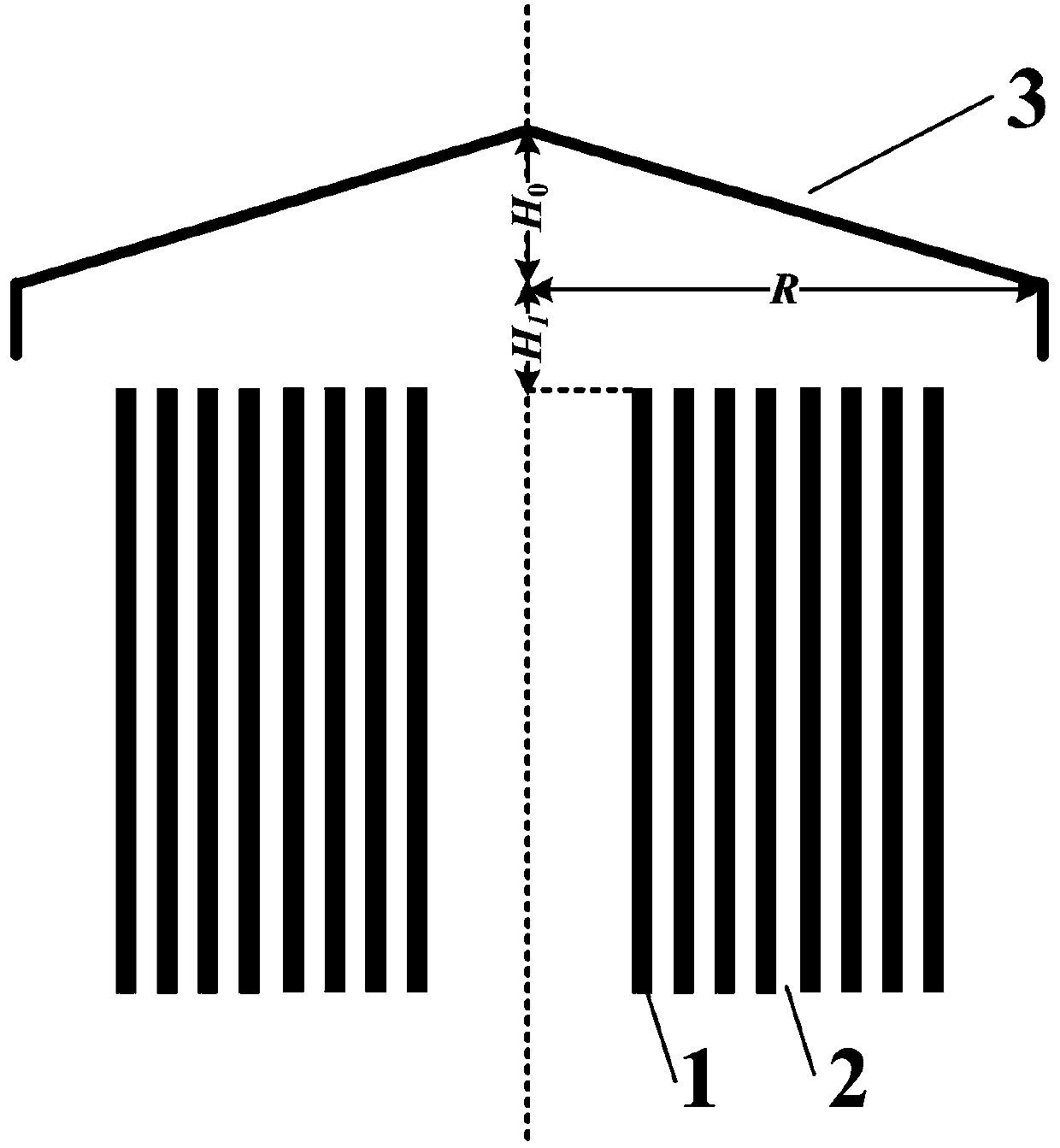
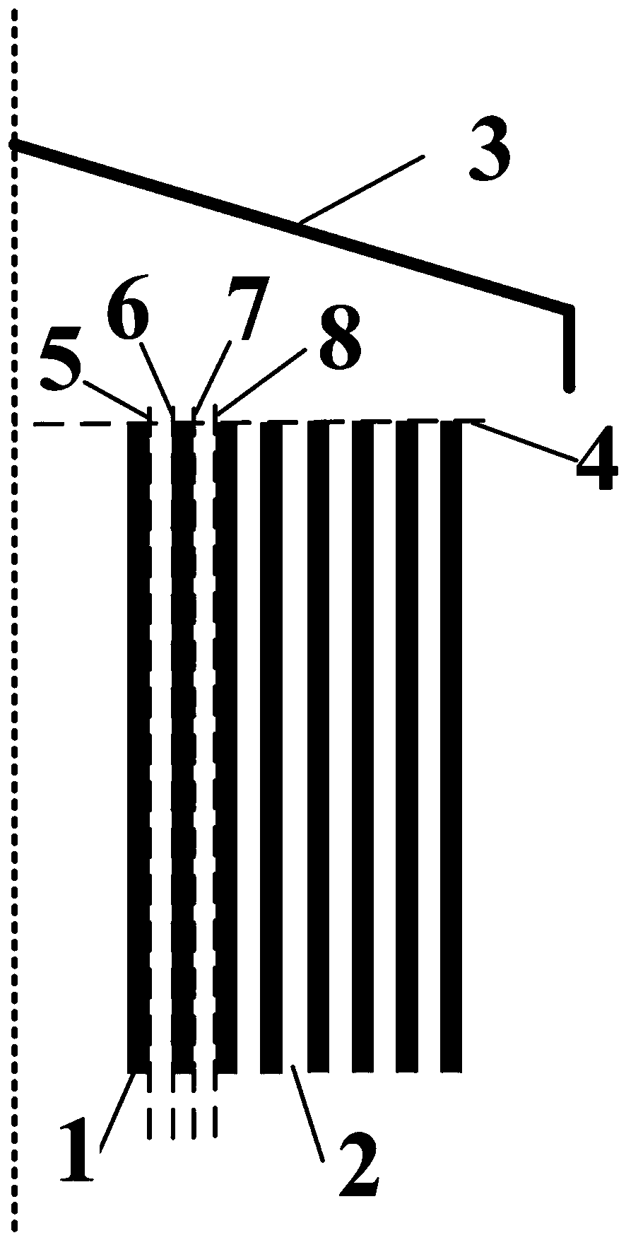
[0045] Such as figure 1 with figure 2 As shown, a single rain-shielding cap is adopted in the embodiment, and the reactor is composed of 10 enveloped coils. The temperature rise calculation method of the reactor with the rain-shielding cap includes the following steps,

[0046] Step 1: According to the characteristics of heat generation and heat dissipation inside the reactor, form the initial design parameters of the reactor; based on the initial design parameters of the reactor, use simulation software such as COMSOL to establish the magnetic field-circuit coupling simulation model of the air-core reactor, and obtain the reactor The magnetic field distribution around the envelope coil and the loss of each envelope;

[0047] Step 2: Establish the flow field-temperature field simulation models of the reactor without the rain cap and the reactor with the rain cap respectively;

[0048] Step 2.1: Establish the flow field-temperature field simulation model of the reactor witho...


PUM


Abstract

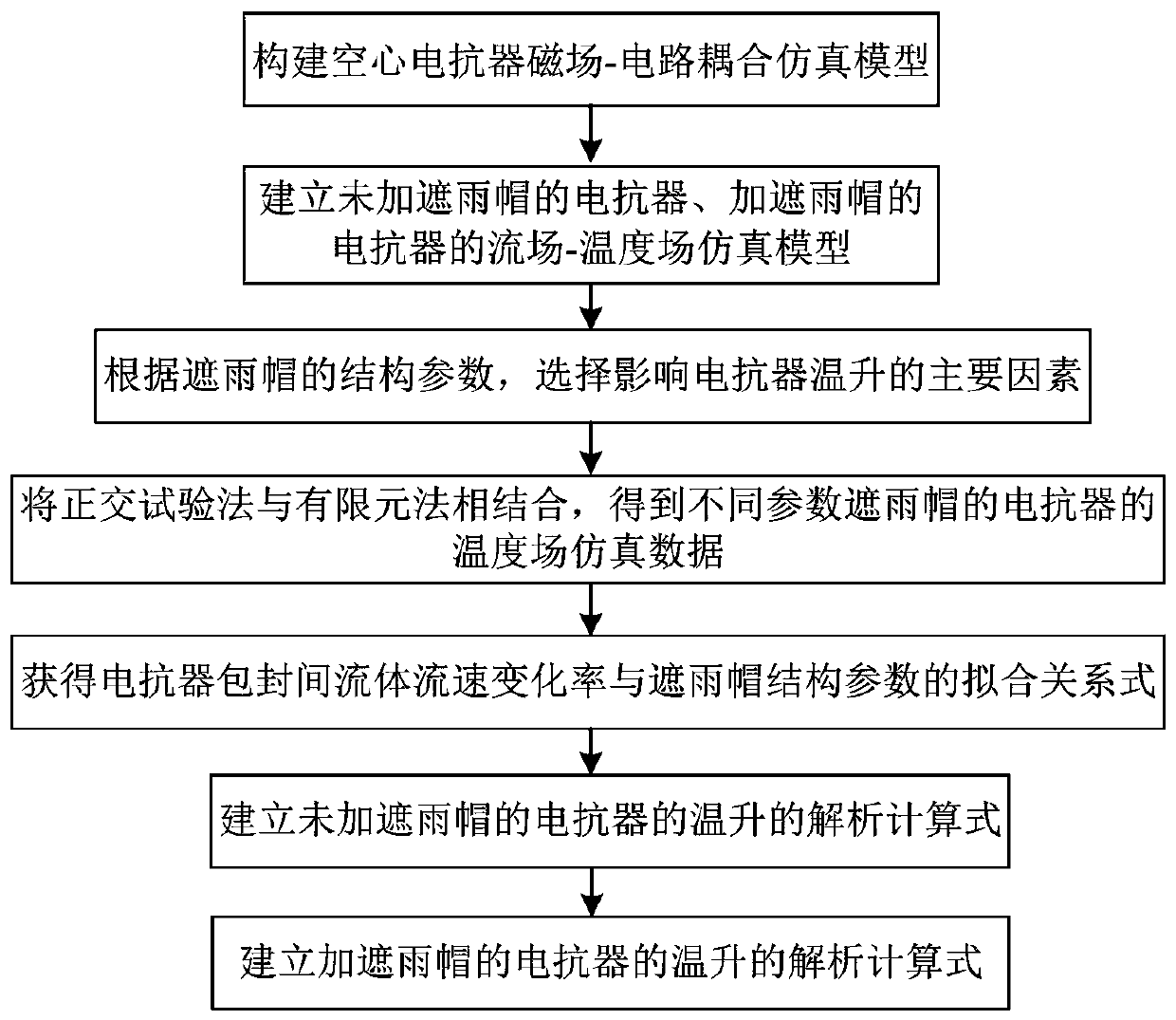
The invention discloses a temperature rise calculation method for an electric reactor with a rain shielding cap. The method comprises: constructing an air-core electric reactor magnetic field-circuitcoupling simulation model; respectively establishing flow field-temperature field simulation models of the reactor without the rain shielding cap and the reactor with the rain shielding cap; selectingmain factors influencing the temperature rise of the reactor; combining an orthogonal test method with a finite element method, and permuting and combining the structural parameters of the rain shielding caps to obtain temperature field simulation data of the reactors of the rain shielding caps with different parameters; fitting the parameter variables to obtain a fitting relational expression between the fluid flow velocity change rate between the reactor encapsulation and the rain shielding cap structure parameters; establishing an analytical calculation formula of the temperature rise of the electric reactor without the rain shielding cap; and obtaining an analytical calculation formula of the temperature rise of the reactor with the rain shielding cap according to the fitting relationbetween the fluid flow rate change rate between the reactor encapsulation and the structure parameters of the rain shielding cap. The method for parsing and calculating the temperature rise of the electric reactor under the action of the rain shielding cap is obtained, and quantitative calculation of the temperature rise of the electric reactor is achieved.

Description

technical field [0001] The invention belongs to the field of reactor temperature rise calculation, and in particular relates to a method for calculating the temperature rise of a reactor with a rain shield. Background technique [0002] Dry-type air-core reactors have become the preferred type of large-scale power reactors due to their simple structure, good linearity, and light weight. During actual operation, reactors often burn out. Relevant studies have shown that excessive local temperature rise is the cause of reactance One of the main reasons for the burnout of the reactor, so the accurate calculation of the temperature rise in the reactor design is very important. The existing temperature rise calculation method mainly obtains the overall temperature rise distribution of the reactor by calculating the average temperature rise from the gas channel to the inner fluid and the fluid-solid temperature difference between the envelope wall and the fluid. Working condition ...

Claims


Application Information

Patent Timeline
IPC IPC(8): G06F17/50
Inventor 袁发庭杨守位唐波丁璨吕凯黄力陈彬
Owner CHINA THREE GORGES UNIV
Learn More