Eureka AIR delivers breakthrough ideas for toughest innovation challenges, trusted by R&D personnel around the world.

Visual plugging evaluation device and use method thereof

A technology for evaluating devices and plugging slurry, which is used in measurement devices, instruments, scientific instruments, etc., can solve the problem that the particle size of the plugging material is difficult to match with the pore size of the formation, and it is impossible to observe the plugging of the leakage channel by the plugging material. Condition, plugging formula and poor matching of pore channels, etc., to achieve the effect of convenient and quick disassembly, easy storage and carrying, uniform metallographic structure and pressure bearing capacity

Pending Publication Date: 2019-11-22
XINJIANG GRAND OILFIELD TECH
View PDF7 Cites 6 Cited by
  • Summary
  • Abstract
  • Description
  • Claims
  • Application Information

AI Technical Summary

Problems solved by technology

Bridge slurry plugging is the most common way to deal with lost circulation in drilling engineering. Before plugging construction, it is necessary to determine the plugging formula according to the leakage rate, leakage volume, annular liquid level and other conditions. One of the difficulties lies in the particle size of the plugging material. Therefore, it is often necessary to evaluate the plugging slurry and adjust the formula according to the demand. However, most of the commonly used plugging evaluation test devices in the prior art are sealing devices, and it is impossible to observe the impact of the plugging material on the leakage. The plugging condition of the channel often causes the problem that the adjusted plugging formula still does not match well with the pore channel

Method used


Image

  • Visual plugging evaluation device and use method thereof
  • Visual plugging evaluation device and use method thereof

Examples


Embodiment 1

[0039] as attached figure 1 As shown, a visual plugging evaluation device includes a simulated wellbore mechanism 1, a simulated formation mechanism 2 and a measurement mechanism 3 connected in sequence;

[0040] Among them, the simulated wellbore mechanism 1 includes a compressed gas source 11 connected in sequence, a compressed gas pipeline 12 and a vertically arranged slurry holding pipe 13, and the compressed gas pipeline 12 is connected to the top of the slurry containing pipe 13; there is a pressure regulating valve at the outlet of the compressed gas source 1 14 and pressure gauge 15;

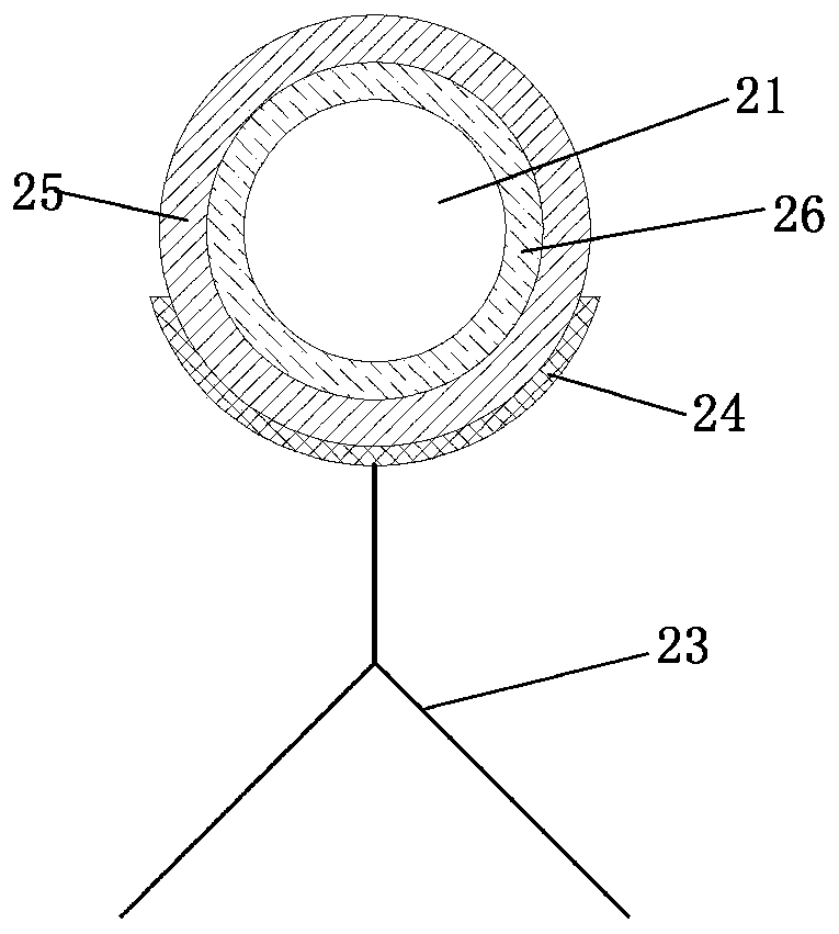
[0041] The simulated formation mechanism 2 includes visual tubes 21 and outlet valves 22 arranged horizontally and connected in sequence; the two ends of the visible tubes 21 have filter screens, and the outer wall is covered with a visible reinforcement layer 25 and a transparent material insulation layer 26;

[0042] It also includes a support frame 23 on which the visible tube 21 is ...

Embodiment 2

[0053] as attached figure 1 As shown, a visual plugging evaluation device includes a simulated wellbore mechanism 1, a simulated formation mechanism 2 and a measurement mechanism 3 connected in sequence;

[0054]Among them, the simulated wellbore mechanism 1 includes a compressed gas source 11 connected in sequence, a compressed gas pipeline 12 and a vertically arranged slurry holding pipe 13, and the compressed gas pipeline 12 is connected to the top of the slurry containing pipe 13; there is a pressure regulating valve at the outlet of the compressed gas source 1 11 and pressure gauge 12;

[0055] The simulated formation mechanism 2 includes visual tubes 21 and outlet valves 22 arranged horizontally and connected in sequence; the two ends of the visible tubes 21 have filter screens, and the outer wall is covered with a visible reinforcement layer 25 and a transparent material insulation layer 26;

[0056] Also include support frame 23 and support plate 24, support plate 24 ...


PUM


Abstract

The invention provides a visual plugging evaluation device and a use method thereof. The device comprises a simulated wellbore mechanism, a simulated formation mechanism and a measuring mechanism which are sequentially connected. The simulated wellbore mechanism comprises a compressed gas source, a compressed gas pipeline and a vertically arranged slurry pipe which are sequentially connected. Thesimulated formation mechanism comprises a visual pipe and an outlet valve which are horizontally arranged and sequentially connected. The measuring mechanism is connected with the outlet valve. The visual plugging evaluation device simulates different pore formations through particle fillers with different diameters, pressurized plugging is performed by using the plugging slurry of certain centration, the plugging process and results of the plugging agent bridging in the pores are observed and the effect of the plugging formula is evaluated. According to the plugging evaluation device, the plugging process can be directly observed and monitored anytime so as to be convenient and easy to use.

Description

technical field [0001] The invention relates to the technical field of petroleum drilling equipment, in particular to a visual plugging evaluation device and a method for using the same. Background technique [0002] Lost circulation is a common and complicated situation in the drilling process. It is a common problem since drilling. Different degrees of lost circulation have occurred in the drilling process in different regions. Severe lost circulation will lead to a drop in well pressure, affecting normal drilling, causing The instability of the wellbore wall induces formation fluid to flow into the wellbore and blowout, resulting in huge economic losses. [0003] At present, technologies such as bridge slurry plugging, high water loss plugging, cement plugging, and gel plugging are mostly used for well leakage control. Bridge slurry plugging is the most common way to deal with lost circulation in drilling engineering. Before plugging construction, it is necessary to dete...

Claims


Application Information

Patent Timeline
Patent Type & Authority Applications(China)
IPC IPC(8): G01N33/00
CPCG01N33/00
Inventor 杨雪峰李前贵何对龙袁锦彪韦青青
Owner XINJIANG GRAND OILFIELD TECH
Why Eureka
Eureka Blog
Learn More