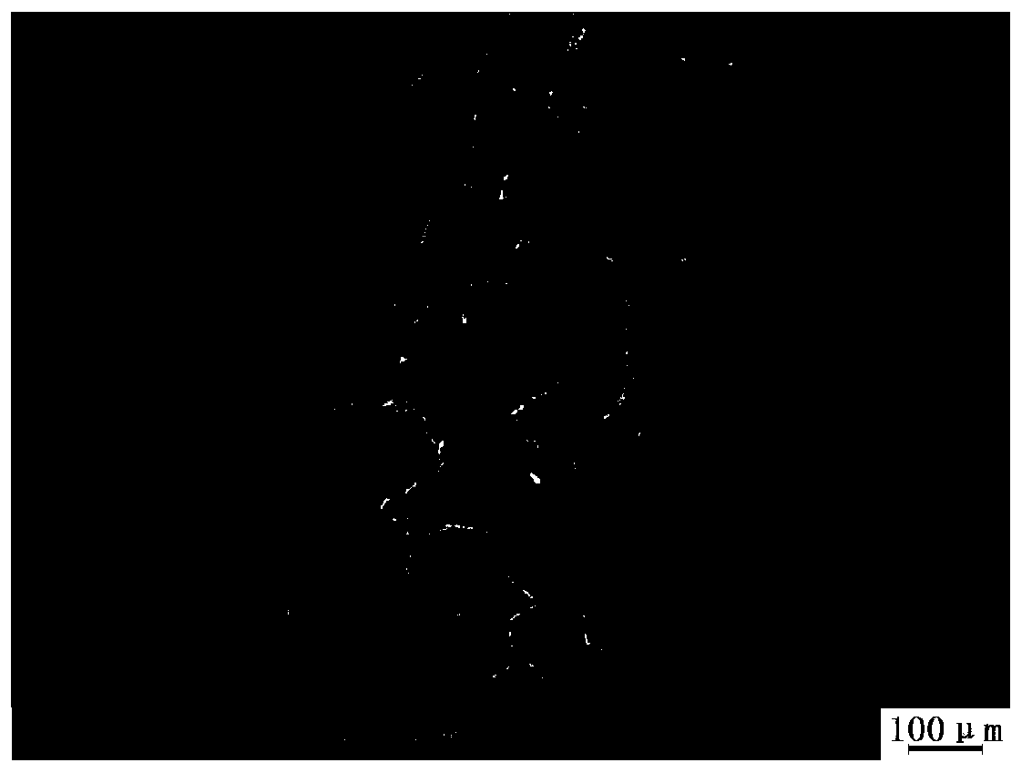
Process for controlling extreme upper-limit Mn content R350HT steel rail flash welding joint structure
A technology of R350HT and welded joints, which is applied in the field of controlling the microstructure of R350HT rail flash welded joints with the upper limit of Mn content, can solve the problems of increasing the martensite content in the joints, and achieve the effect of simple control process and good prospects for popularization and application.
- Summary
- Abstract
- Description
- Claims
- Application Information
AI Technical Summary
Problems solved by technology
Method used
Image
Examples
Embodiment 1
[0033] Using the flash welding process with heat input of 8.9MJ and upsetting amount of 15.3mm, the European standard R350HT heat-treated steel rail with a mass fraction of Mn of 1.15% (C content is in the middle and lower limits, Si≤0.30wt%, Rm≥1175MPa, A ≥9%, tread hardness ≥350HB) for flash welding. After the flash welding is completed, first use an infrared thermometer to measure the temperature at the center of the weld seam of the naturally cooled rail joint, and when the temperature drops to 585°C, immediately use an aluminosilicate fiber cotton heat insulation device with a thickness ≥ 30mm Insulate the 200mm area on both sides of the joint fusion line; continue to monitor the joint temperature during this process, and remove the device when the temperature at the center of the welding seam on the driving surface is lower than 250°C, and finally place the joint in the air to cool naturally to room temperature .
[0034] According to EN 14587.2, the joints obtained by ...
Embodiment 2
[0036] Using the flash welding process with heat input of 9.5MJ and upsetting amount of 16.0mm, the European standard R350HT heat-treated steel rail with a mass fraction of Mn of 1.21% (C content is in the middle and lower limits, Si≤0.30wt%, Rm≥1175MPa, A ≥9%, tread hardness ≥350HB) for flash welding. After the flash welding is completed, first use an infrared thermometer to measure the temperature at the center of the weld seam of the naturally cooled rail joint, and when the temperature drops to 575°C, immediately use an aluminosilicate fiber cotton heat insulation device with a thickness ≥ 30mm Insulate the 200mm area on both sides of the joint fusion line; continue to monitor the joint temperature during this process, and remove the device when the temperature at the center of the welding seam on the driving surface is lower than 250°C, and finally place the joint in the air to cool naturally to room temperature .
[0037] According to EN 14587.2, the joints obtained by ...
Embodiment 3
[0039] Using the flash welding process with heat input of 8.5MJ and upsetting amount of 15.5mm, the European standard R350HT heat-treated steel rail with a mass fraction of Mn of 1.18% (C content is in the middle and lower limits, Si≤0.30wt%, Rm≥1175MPa, A ≥9%, tread hardness ≥350HB) for flash welding. After the flash welding is completed, first use an infrared thermometer to measure the temperature at the center of the weld seam of the naturally cooled rail joint, and when the temperature drops to 580°C, immediately use an aluminosilicate fiber cotton insulation device with a thickness of ≥30mm Insulate the 200mm area on both sides of the joint fusion line; continue to monitor the joint temperature during this process, and remove the device when the temperature at the center of the welding seam on the driving surface is lower than 250°C, and finally place the joint in the air to cool naturally to room temperature .
[0040] According to EN 14587.2, the joints obtained by the...
PUM
| Property | Measurement | Unit |
|---|---|---|
| thickness | aaaaa | aaaaa |
| hardness | aaaaa | aaaaa |
Abstract
Description
Claims
Application Information
 - R&D
- Intellectual Property
- Life Sciences
- Materials
- Tech Scout
- Unparalleled Data Quality
- Higher Quality Content
- 60% Fewer Hallucinations
Browse by: Latest US Patents, China's latest patents, Technical Efficacy Thesaurus, Application Domain, Technology Topic, Popular Technical Reports.
© 2025 PatSnap. All rights reserved.Legal|Privacy policy|Modern Slavery Act Transparency Statement|Sitemap|About US| Contact US: help@patsnap.com

