
Oil spraying and water spraying dual-purpose device for tire face of road roller tire

A technology for tire tread and dual-purpose device, which is applied to spray devices, spray devices with movable outlets, roads, etc., can solve the problems of loud construction noise, inability to control the measurement of lubrication in real time, easy oil leakage, etc., to reduce operation. Burden, improving construction efficiency and pavement quality, and preventing oil leakage

Pending Publication Date: 2019-11-22
徐州宏嵩机电设备有限公司
View PDF4 Cites 0 Cited by
  • Summary
  • Abstract
  • Description
  • Claims
  • Application Information

AI Technical Summary

Problems solved by technology

[0002] During the working process of the road roller, there is always a problem that plagues the construction personnel. Whether it is a steel wheel roller or a rubber wheel roller, there is a situation where asphalt stones adhere to the steel wheel (rubber wheel) tread. If it is not cleaned in time, it will seriously affect the road surface. The construction quality is poor, and even the compacted road surface needs to be dug out for re-construction, resulting in a great waste of manpower and material resources.
A common solution at the construction site is to let the construction workers hold a mop dipped in lubricating oil and walk back and forth with the roller, and apply lubricating oil on the tires, but this brings serious safety hazards, and construction accidents will occur if they are not careful , resulting in the death of the worker
[0003] Chinese invention patent CN201510301634, Chinese utility model CN201621116526, CN201821266671 and CN201811028074 respectively disclose the dual-purpose device of fuel spraying / water spraying on the tire tread of road roller, but the nozzles of these fuel spraying devices are all fixed, and the tread fuel spraying directly facing the nozzle is relatively difficult. There are more treads on both sides, which leads to uneven fuel injection. Although some nozzles are fan-shaped nozzles, there is still the problem of more fuel injection in the middle of the tread and less fuel injection on both sides of the tread.
In addition, the above-mentioned existing fuel injection devices mostly use a single valve for fuel injection control, and the nozzles are prone to oil leakage after fuel injection, which affects the quality of road construction
[0004] In addition, the fuel injection devices disclosed in the above-mentioned patents all have their control devices installed on the cockpit of the road roller to move with the road roller, and the driver performs the control of fuel injection / stop fuel injection, but in the actual engineering site, the operating driver cannot Seeing the actual adhesion of the tires during work, it is impossible to control the measurement of lubrication in real time. The ground staff needs to report the condition of the tire tread to the driver. However, the general construction noise on the construction site is too loud, and the driver cannot be notified in time to inject oil / stop injection operation

Method used


Image

  • Oil spraying and water spraying dual-purpose device for tire face of road roller tire
  • Oil spraying and water spraying dual-purpose device for tire face of road roller tire
  • Oil spraying and water spraying dual-purpose device for tire face of road roller tire

Examples


Embodiment 1

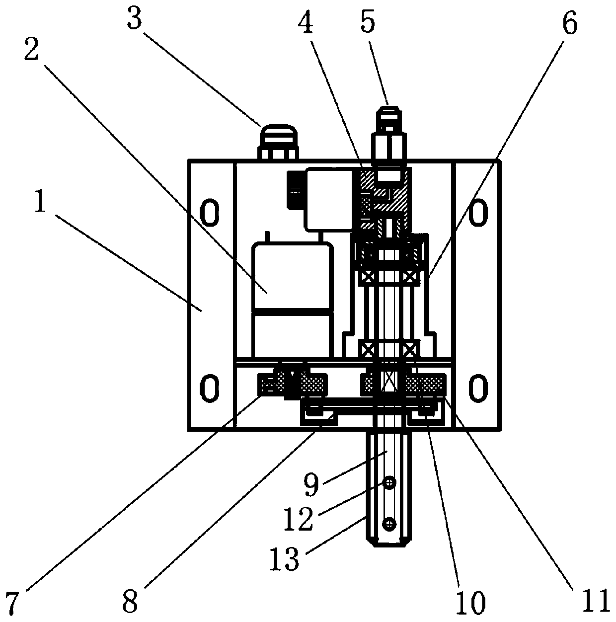
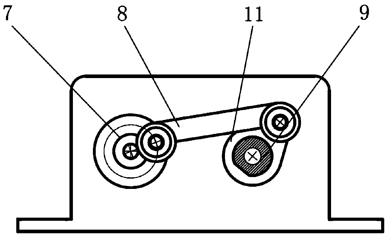
[0027] Such as figure 1 As shown, the tire tread oil / water spray dual-purpose device of a road roller includes a housing bracket 1, a two-position two-way electromagnetic reversing valve 4, a bearing assembly, an oil injection shaft 8, an eccentric wheel 7, a connecting rod 8, and a rocker 11. Gear motor 2. Oil supply device and control device (the control device can adopt industrial control switch, PLC or single-chip microcomputer, such as STM32, etc.). There are outlet holes 3 and oil inlet joints 5 on the edge of the housing bracket 1 and a protective cover 13 is installed. The geared motor 2, the two-position two-way electromagnetic reversing valve 4 and the data input end of the oil supply device are respectively connected to the control device through signal lines, and the signal lines connected to the geared motor 2 and the two-position two-way electromagnetic directional valve 4 are connected by The hole 3 extends out of the housing bracket 1, and the geared motor 2 i...

Embodiment 2

[0032] The difference between this embodiment and Embodiment 1 is that the controller is a remote control device, the remote control device includes a remote control switch and a remote control, the remote control switch includes a receiving module and several relays, the receiving module and the relay are located on the same PCB, two-position The electromagnetic reversing valve 4, the reduction motor 2, and the DC motor are respectively connected with the relay, and the signal frequency of the remote controller is 315MHz or 433MHz.

[0033] When fuel injection is required, within an appropriate distance, press the start button on the remote controller, and the remote control switch will simultaneously open the two-way electromagnetic reversing valve 4, the reduction motor 2 and the DC motor, and the fuel injection device will start to inject fuel. When oiling, press the stop key on the remote controller, the remote control switch synchronously closes the two-way electromagneti...


PUM


Abstract

The invention discloses an oil spraying and water spraying dual-purpose device for the tire face of a road roller tire. The device comprises a shell support, two-position two-way electromagnetic reversing valve, a bearing assembly, an oil spraying shaft, an eccentric wheel, a connecting rod, a rocking rod, a gear motor, an oil supply device and a control device. When the gear motor is started, theeccentric wheel is rotated to drive the oil spraying shaft through the connecting rod and the rocking rod to do left-right swinging reciprocating motion. According to the oil spraying and water spraying dual-purpose device for the tire face of the road roller tire, a nozzle can swing left and right to spray oil or water to the tire face of the tire evenly; the nozzle is controlled by the two-position two-way electromagnetic reversing valve to be opened and closed, and the nozzle is prevented from leaking oil after spraying oil. The device is started or stopped at appropriate time through a remote controller according to real-time working conditions by ground operators, therefore, the operation burden of a road roller driver can be relieved, and construction efficiency and road quality canbe greatly improved.

Description

technical field [0001] The invention relates to an oil spraying or water spraying device for a steel wheel or a rubber tire tread of a tire road roller, in particular to an oil spraying or water spraying device for the tire tread of a road roller. Background technique [0002] During the working process of the road roller, there is always a problem that plagues the construction personnel. Whether it is a steel wheel roller or a rubber wheel roller, there is a situation where asphalt stones adhere to the steel wheel (rubber wheel) tread. If it is not cleaned in time, it will seriously affect the road surface. In order to improve the construction quality, even the compacted road surface needs to be dug out for re-construction, resulting in a great waste of manpower and material resources. A common solution at the construction site is to let the construction workers hold a mop dipped in lubricating oil and walk back and forth with the roller, and apply lubricating oil on the ti...

Claims


Application Information

Patent Timeline
Patent Type & Authority Applications(China)
IPC IPC(8): B05B3/14B05B12/00E01C19/23
CPCB05B3/14B05B12/00E01C19/238
Inventor 谢洪彬
Owner 徐州宏嵩机电设备有限公司
Learn More