Hydraulic steering system and assembling method thereof
A steering hydraulic and steering gear technology, applied in steering mechanism, fluid steering mechanism, power steering mechanism, etc., can solve problems such as unfavorable hydraulic oil flow and poor stabilization effect, and achieve enhanced firmness, facilitate hydraulic oil flow, and ensure normal operation. The effect of running
- Summary
- Abstract
- Description
- Claims
- Application Information
AI Technical Summary
Problems solved by technology
Method used
Image
Examples
Embodiment 1
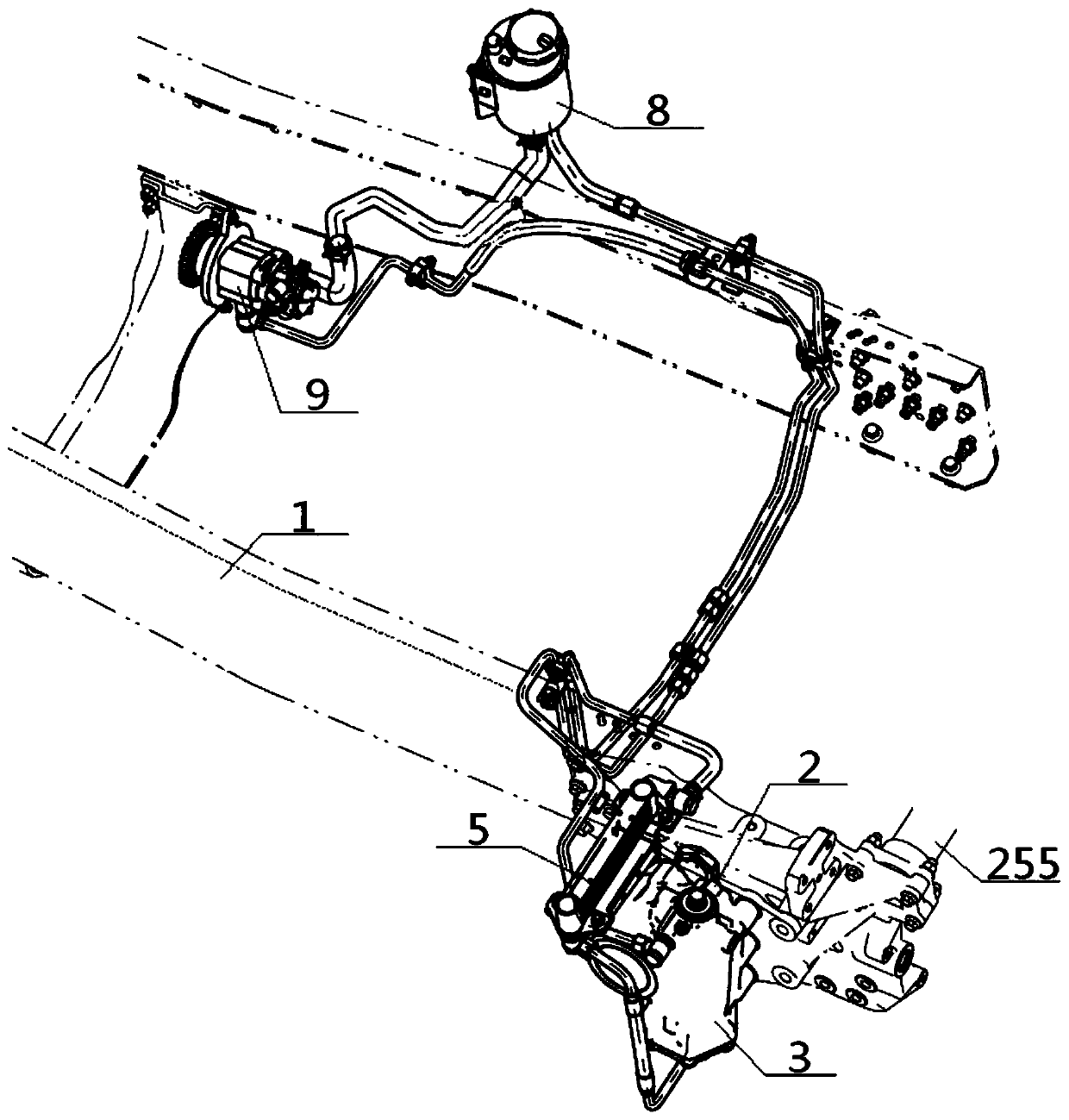
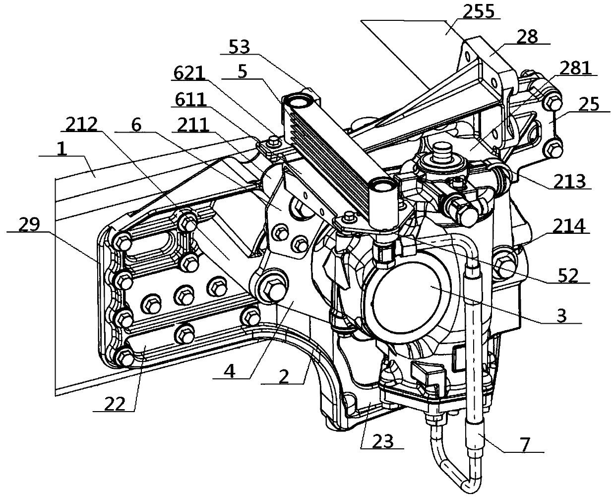
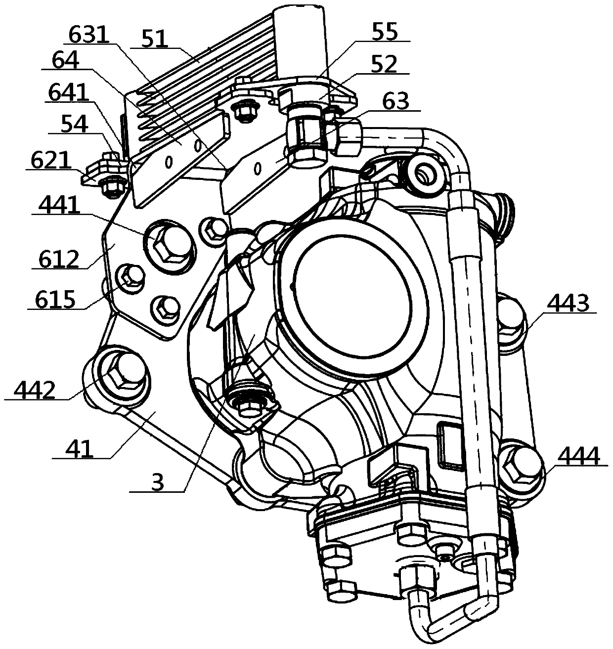
[0061] see Figure 1 to Figure 11 , a steering hydraulic system, comprising a steering gear 3, a radiator 5, a steering oil tank 8 and a steering pump 9, the radiator oil outlet 53 on the radiator 5 passes through the steering oil tank 8, the steering pump 9, the steering After the engine 3 is connected with the radiator oil inlet 52 on the radiator 5 for external pipeline connection, the steering gear 3 is connected with the frame longitudinal beam 1 through the steering gear bracket 4, and the steering gear bracket 4 is connected with the radiator bracket 6 through the radiator bracket 6. The steering hydraulic system also includes an integrated connecting bracket 2 and a casting pillar 21, and the integrated connecting bracket 2 includes a beam casting slave plate 22, a casting machine slave plate 23, and a beam connecting plate 25 connected in sequence. Steering machine support 4 comprises machine support plate body 41 and the output shaft hole 42 that offers on it, frame ...
Embodiment 2
[0064] Basic content is the same as embodiment 1, the difference is:
[0065] The number of the frame connecting holes 43 and the frame connecting holes 44 is multiple, and the area surrounded by all the frame connecting holes 43 on the frame support plate 41 is the frame connecting area 45, and all the frame The area surrounded by the connection hole 44 on the machine bracket plate body 41 is the frame connection area 46, and the output shaft hole 42 falls into the frame connection area 45 in whole or in part, and the frame connection area 45 is located in the frame connection area 46, the upper left corner of the frame connection area 46 is provided with an auxiliary connection hole 40; the heat dissipation bracket 6 includes a bracket body 61 and a bracket auxiliary body 62 that are both L-like structures, and the bracket body 61 includes a main body horizontal plate 611 and The main body vertical plate 612, the bracket auxiliary body 62 includes the auxiliary body horizont...
Embodiment 3
[0067] Basic content is the same as embodiment 2, the difference is:
[0068] The casting pillar 21 includes an upper left casting pillar 211, a lower left casting pillar 212, an upper right casting pillar 213 and a lower right casting pillar 214. Correspondingly connected with the left lower frame hole 442, the top of the upper right casting pillar 213 is connected with the right upper frame hole 443, and the top of the right lower casting pillar 214 is correspondingly connected with the right lower frame hole 444; the left upper casting pillar 211 is connected with the right upper casting The distance between struts 213, and the distance between lower left casting strut 212 and lower right casting strut 214 are greater than the spacing between upper left casting strut 211, lower left casting strut 212 and the spacing of upper right casting strut 213, lower right casting strut 214. The bottom end of the upper left casting pillar 211 is connected to the bottom end of the upper...
PUM
 Abstract
Description
Claims
Application Information
 - R&D
- Intellectual Property
- Life Sciences
- Materials
- Tech Scout
- Unparalleled Data Quality
- Higher Quality Content
- 60% Fewer Hallucinations
Browse by: Latest US Patents, China's latest patents, Technical Efficacy Thesaurus, Application Domain, Technology Topic, Popular Technical Reports.
© 2025 PatSnap. All rights reserved.Legal|Privacy policy|Modern Slavery Act Transparency Statement|Sitemap|About US| Contact US: help@patsnap.com


