A tunnel type super (sub) critical CO 2 Waterless scouring device
A tunnel type, wool scouring technology, applied in the recovery/refining of fatty substances, washing/scouring of loose animal wool fibers, chemical post-treatment of fibers, etc., can solve the problems of difficult extraction of organic pollutants, high water consumption and energy consumption, grease, High pollution and other problems, to achieve efficient recycling, meet the requirements of clean production, and solve the effects of high water consumption and high pollution problems
- Summary
- Abstract
- Description
- Claims
- Application Information
AI Technical Summary
Problems solved by technology
Method used
Image
Examples
Embodiment 1
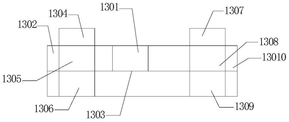
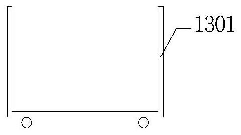
[0025] A tunnel-type scouring bin, the tunnel-type scouring bin 13 includes a scouring car 1301, a scouring car positioner I 1302, a guide rail 1303, a fluid passage I 1304, a wetting passage 1305, an impurity collector 1306, a fluid passage II 1307, Cleaning channel 1308, grease settler 1309, scourer positioner II 13010;
[0026] The fluid channel I 1304 is provided with a lower cover plate I with a porous structure, and the aperture of the lower cover plate I is 0.5mm;
[0027] The fluid channel I 1304, the wetting channel 1305 and the impurity collector 1306 form a wetting pool;
[0028] The fluid channel II 1307 is provided with a lower cover plate II with a porous structure, and the aperture of the lower cover plate II is 0.5mm;
[0029] The fluid passage II 1307, the cleaning passage 1308 and the grease settler 1309 form a cleaning pool;
[0030] The guide rail 1303 sequentially passes through the scourer positioner I1302, the wetting pool, the cleaning pool, and the s...
Embodiment 2
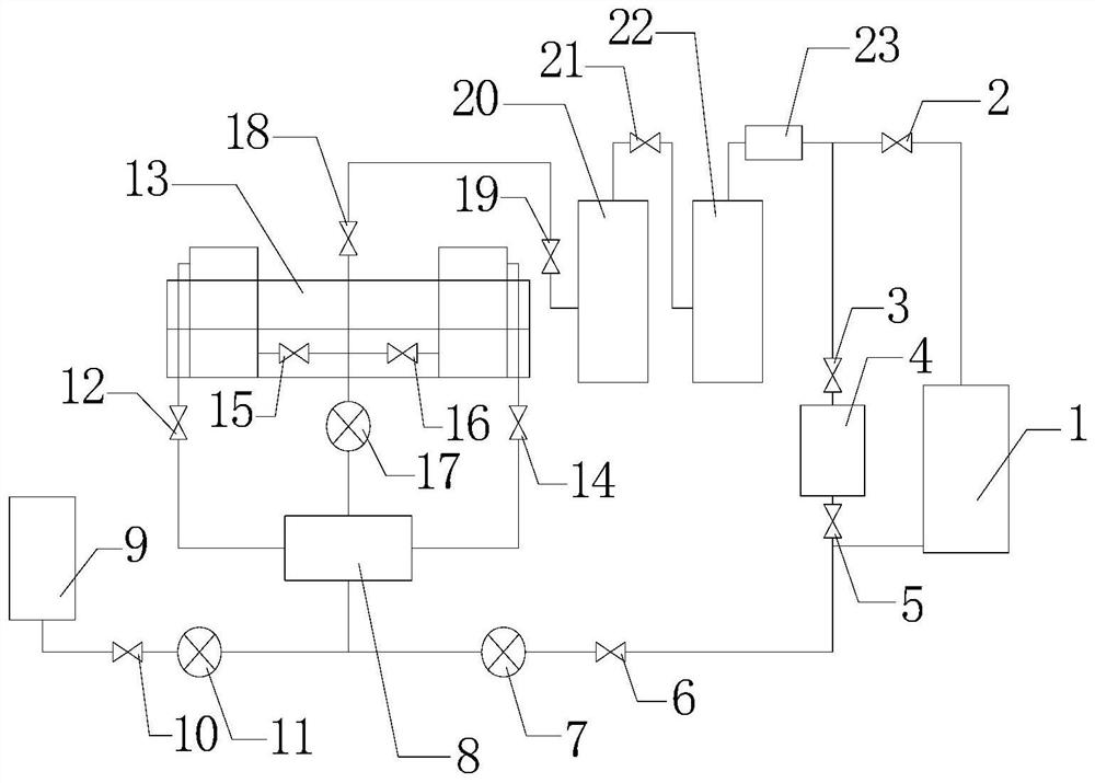
[0036] A tunnel type super(sub)critical CO 2 Waterless wool scouring device, the tunnel type super (sub)critical CO 2 Waterless scouring unit including CO 2 Liquid storage tank 1, condenser 4, CO 2 Booster pump 7, heat exchanger 8, solvent storage tank 9, metering pump 11, tunnel type wool scouring chamber 13 described in embodiment 1, CO 2 Circulation pump 17, separation kettle I 20, separation kettle II 22, adsorber 23;
[0037] The CO 2 Outlet I of liquid storage tank 1 passes through valve I2, valve II3, condenser 4, valve III5, valve IV6, CO 2 The booster pump 7 is connected to the inlet I of the heat exchanger 8;
[0038] The solvent storage tank 9 is connected to the inlet I of the heat exchanger 8 through the valve V10 and the metering pump 11 in sequence;
[0039] The outlet I of the heat exchanger 8 is connected to the fluid passage I1304 of the tunnel-type wool scouring chamber 13 through a valve VI12;
[0040] The outlet II of the heat exchanger 8 is connected...
Embodiment 3
[0048] Utilize the CO of the device described in Example 2 2 An anhydrous method for scouring wool, said method comprising the steps of:
[0049] Liquid CO 2 transported to CO 2 In the liquid storage tank 1, transport the co-solvent to the solvent storage tank 9, and transport the initially loosened wool to the wool scourer 1301;
[0050] When washing wool, the washing car 1301 enters the wetting passage 1305 along the guide rail 1303, and the electromagnet is turned on, so that the top of the washing car 1301 is magnetically sealed with the fluid passage I 1304, and the bottom of the washing car 1301 is magnetically sealed with the impurity collector 1306. Open valve Ⅰ2, valve Ⅱ3, valve Ⅲ5, valve Ⅳ6, valve Ⅴ10, valve Ⅵ12, valve Ⅷ15, and close other valves to make CO 2 Liquid CO in liquid storage tank 1 2 Via condenser 4 → CO 2 The booster pump 7 is then mixed with the co-solvent, heated by the heat exchanger 8, and enters the super (sub)critical CO 2 state, and flow int...
PUM
| Property | Measurement | Unit |
|---|---|---|
| pore size | aaaaa | aaaaa |
| pore size | aaaaa | aaaaa |
| pore size | aaaaa | aaaaa |
Abstract
Description
Claims
Application Information
 - R&D
- Intellectual Property
- Life Sciences
- Materials
- Tech Scout
- Unparalleled Data Quality
- Higher Quality Content
- 60% Fewer Hallucinations
Browse by: Latest US Patents, China's latest patents, Technical Efficacy Thesaurus, Application Domain, Technology Topic, Popular Technical Reports.
© 2025 PatSnap. All rights reserved.Legal|Privacy policy|Modern Slavery Act Transparency Statement|Sitemap|About US| Contact US: help@patsnap.com


