Pipe electroplating device

A technology for electroplating equipment and pipes, applied in the electrolytic process, electrolytic components, etc., can solve the problems of unqualified copper pipe size, pipe burst, poor fluidity of electroplating liquid, etc.

Pending Publication Date: 2019-11-19
FOSHAN SHUNDE DISTRICT JIEYONG ELECTRIC IND
View PDF0 Cites 1 Cited by
  • Summary
  • Abstract
  • Description
  • Claims
  • Application Information

AI Technical Summary

Problems solved by technology

[0003] 1. Due to the soft material of pure copper, the copper tube is easily deformed when it is pressed by external force, resulting in unqualified size of the copper tube and affecting the installation;
[0004] 2. Copper powder will be produced during the chamfering process of the copper tube. The copper powder adheres to the inner wall of the copper tube and is difficult to clean. The residual copper powder will affect the operation of the compressor;
[0005] 3. When the air conditioner is running, the copper pipe needs to bear a certain pressure, and the copper pipe has limited pressure resistance, so there is a certain risk of pipe explosion during operation
The problem is that during the electroplating process, after the copper ions in the electroplating liquid inside the steel pipe are consumed, since the steel pipe is a slender tube, the fluidity of the electroplating liquid inside the steel pipe is poor, resulting in a slow replenishment of copper ions, and the electroplating liquid inside and outside the steel pipe is not stable. Uniform, the plating rate difference between the outer wall and the inner wall of the steel pipe is large, the plating effect of the inner wall of the steel pipe is poor, and the copper layer on the inner wall of the steel pipe does not meet the requirements, there are certain limitations

Method used


Image

  • Pipe electroplating device
  • Pipe electroplating device
  • Pipe electroplating device

Examples


Embodiment Construction

[0032] The present invention will be further described below in conjunction with the accompanying drawings and embodiments.

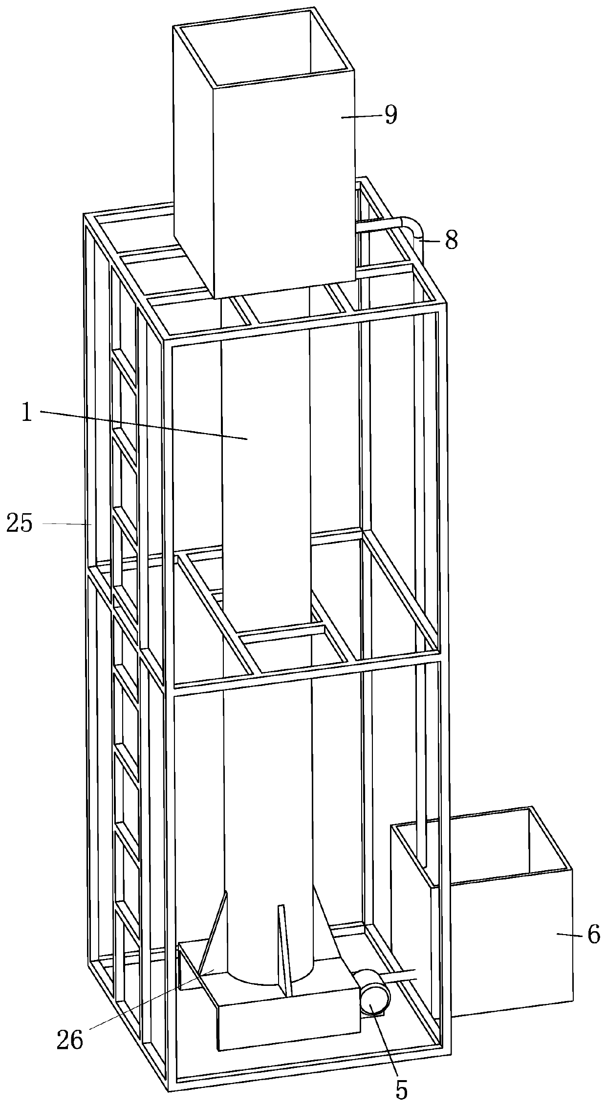
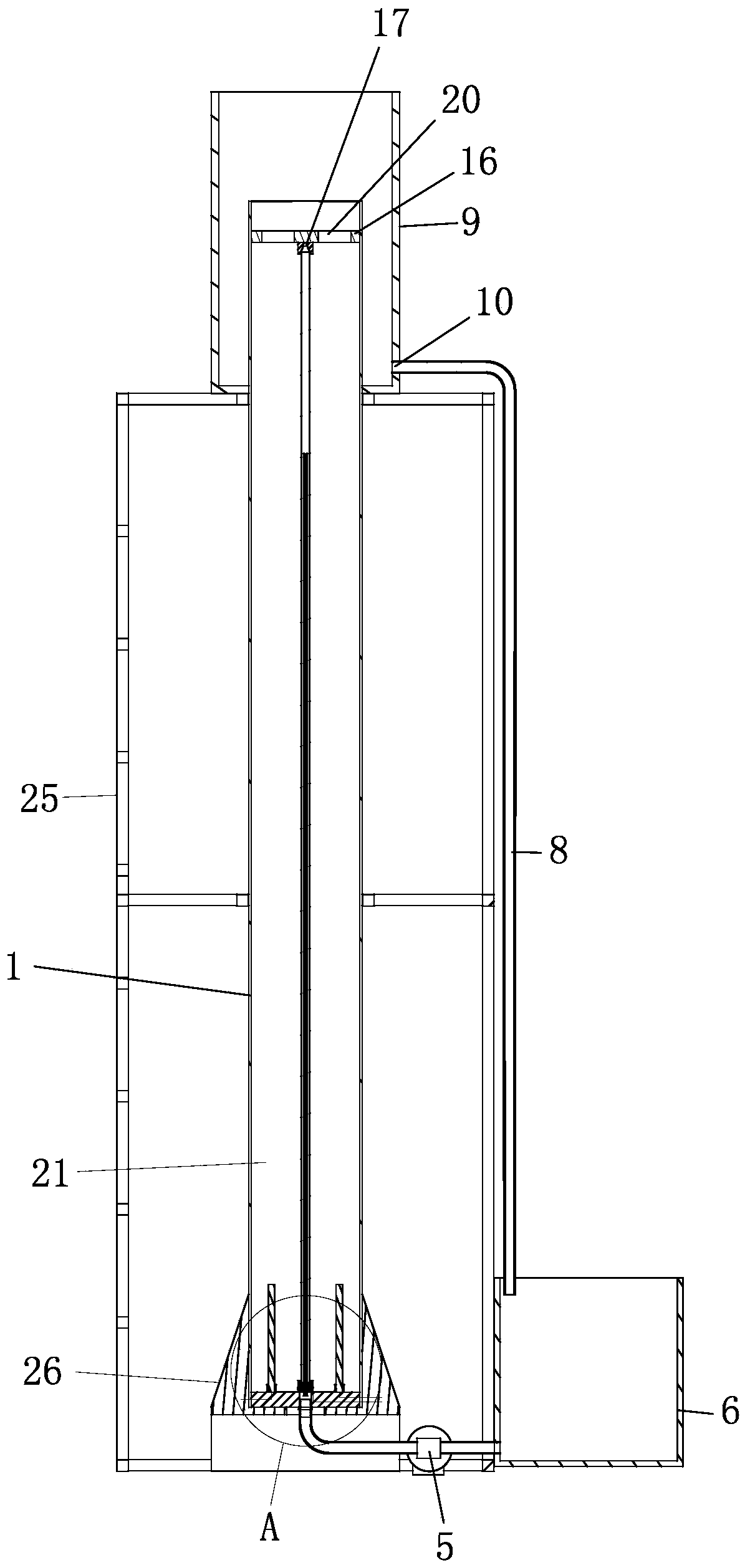
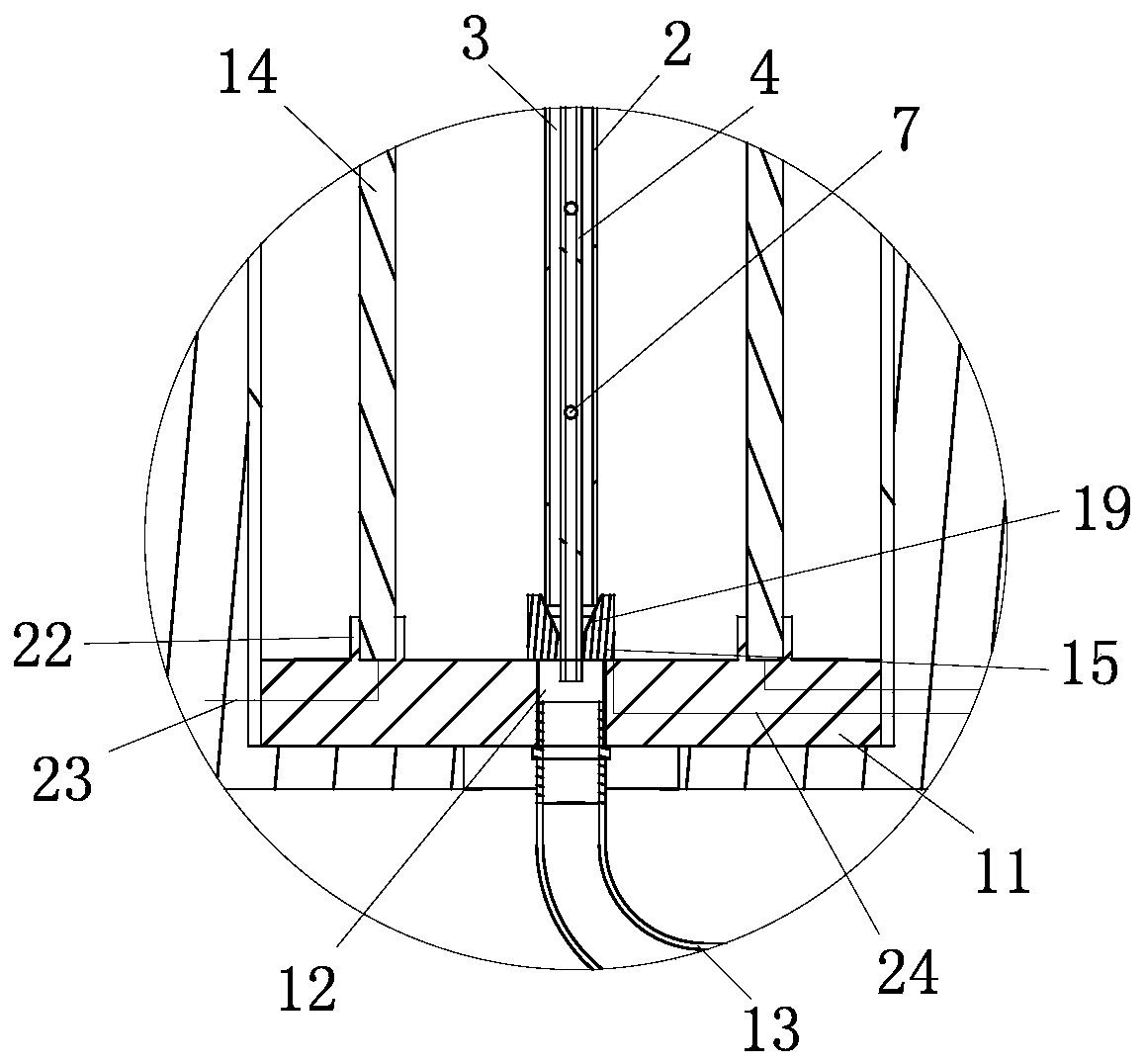
[0033] see Figure 1-Figure 4 , the pipe electroplating equipment includes an electroplating tank 1 with a chemical solution (ie, electroplating solution) inside and a tube body 2 arranged in the electroplating tank 1 and placed in the chemical solution. The inside of the tube body 2 forms an inner wall electroplating section 3, and the tube An outer wall electroplating section 21 is formed between the outer surface of the body 2 and the inner wall of the electroplating tank 1, and also includes a feeding device for delivering chemical liquid to the inner wall electroplating section 3;

[0034] During the electroplating process of this pipe electroplating equipment, the feeding device continuously delivers the chemical liquid to the inside of the pipe body 2 to supplement the copper ions consumed in the electroplating process of the inner wall electropl...


PUM


Abstract

The invention provides a pipe electroplating device. The pipe electroplating device comprises an electroplating tank and a pipe body, wherein the inner part of the electroplating tank is filled with chemical liquid; the pipe body is arranged in the electroplating tank and is placed in the chemical liquid; the inner part of the pipe body forms an inner wall electroplating interval; the pipe electroplating device also comprises a feeding device for conveying the chemical liquid in the inner wall electroplating interval; the feeding device comprises an infusion pipe, a power pump and a chemical liquid tank, which are communicated with one another; the inner part of the chemical liquid tank is filled with the chemical liquid; the infusion pipe extends into the pipe body; a plurality of liquidoutlets are formed in the side of the infusion pipe; and the liquid outlets are distributed at intervals in the length direction of the infusion pipe.

Description

technical field [0001] The invention relates to the field of electroplating processing, in particular to electroplating equipment for copper-coated steel pipes for air conditioners. Background technique [0002] The three-meter tubes used in air conditioners generally use pure copper tubes. The production process of pure copper tubes is generally to cut straight copper tubes into specified lengths, perform double-end chamfering and deburring, and then carry out subsequent molding and processing. In actual use, the two ends of the copper pipe are respectively welded and sealed with corresponding pipe materials. The use of copper tubes has the following disadvantages: [0003] 1. Due to the soft material of pure copper, the copper tube is easily deformed when it is pressed by external force, resulting in unqualified size of the copper tube and affecting the installation; [0004] 2. Copper powder will be produced during the chamfering process of the copper tube. The copper p...

Claims


Application Information

Patent Timeline
IPC IPC(8): C25D7/04C25D17/00C25D5/08
CPCC25D7/04C25D17/00C25D5/08
Inventor 雷勋华李龙祥李兵彭亮
Owner FOSHAN SHUNDE DISTRICT JIEYONG ELECTRIC IND
Why Eureka
Try Eureka