Electrolytic copper foil surface processor and working method thereof

A technology of surface treatment machine and electrolytic copper foil, which is applied in the direction of electrolytic process, electrolytic components, dry cargo handling, etc. It can solve the problems of electrolytic copper foil not up to standard, excessive traction force, and change of residence time, so as to improve electroplating efficiency and improve Production quality, smoothness improvement effect

Pending Publication Date: 2021-03-19
洪田科技有限公司
View PDF0 Cites 1 Cited by
  • Summary
  • Abstract
  • Description
  • Claims
  • Application Information

AI Technical Summary

Problems solved by technology

[0002] The electrolytic copper foil surface treatment machine is mainly composed of an uncoiling device, an intermediate treatment tank section, a drying box, a winding device and a control device; the unwinder will discharge the copper foil to be processed, and the intermediate treatment tank Pickling-roughening first-curing first-roughening second-curing second-water washing-galvanizing-water washing-chrome plating-water washing first-water washing second treatment for copper foil, and the drying box dries the treated copper foil , the copper foil after drying is rewound through the winding machine; the surface treatment of electrolytic copper foil is an advanced treatment process commonly used in the production of finished electrolytic copper foil in the world at present; in the process of surface treatment of electrolytic copper foil, due to the Thin and wide, its general specification is 12um--35um×1295mm, excessive traction, uneven tension or out-of-synchronization of the rollers can cause the copper foil to be broken or torn. Integrity of quality and continuity of process, a large number of tension sensors, tension controllers, tension amplifiers, servo drives and controllers are used in the existing production lines of electrolytic copper foil surface treatment machines; The electrolytic copper foil will be broken or torn, and in order to make the electrolytic copper foil better conveyed, there will be a water squeezing mechanism driven by the copper foil above the conductive roller to improve its traction, but sometimes, the electrolytic copper foil The copper foil will slip with the water squeezing roller of the water squeezing mechanism, which will cause wrinkles on the surface of the electrolytic copper foil and affect the quality of the electrolytic copper foil
[0003] When the existing electrolytic copper foil is processed, the rough surface of the copper foil is made downward, and the metal in the electrolyte is transferred to the rough surface of the copper foil through the electroplating tank. Finally, its electrolytic surface will directly contact with the conductive roller (cathode roller), which will cause a large number of burrs on the electroplated surface of the copper foil passing through the conductive roller. When preparing electrolytic copper foil copper clad laminate (CCL) or printed circuit board (PCB) It is necessary to attach an insulating layer to the rough surface of the electrolytic copper foil, and then compound it with other materials. These burrs will pierce the insulating layer, resulting in the failure of production of copper clad laminates (CCL) or printed circuit boards (PCB). Therefore, electrolytic Copper foil is not up to standard
[0004] And when the sticky roller is replaced, it needs to be shut down to replace the sticky roll, but the stoppage will change the residence time of the copper foil in one of the processing procedures, resulting in the copper foil after treatment cannot be guaranteed. Consistency, affecting the quality of copper foil

Method used


Image

  • Electrolytic copper foil surface processor and working method thereof
  • Electrolytic copper foil surface processor and working method thereof
  • Electrolytic copper foil surface processor and working method thereof

Examples


Embodiment Construction

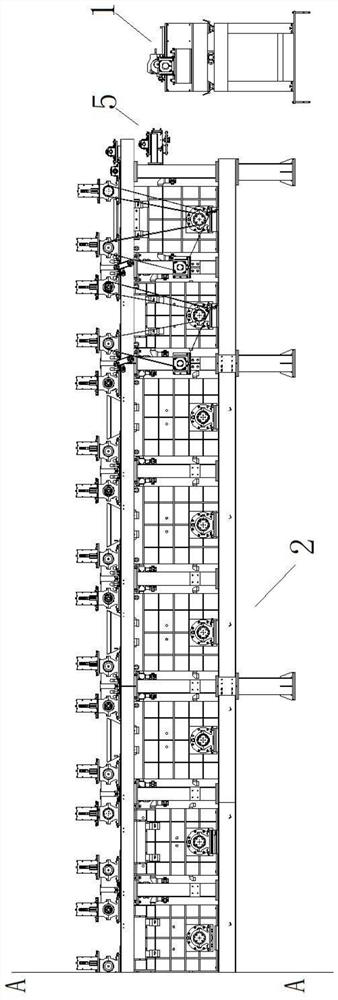
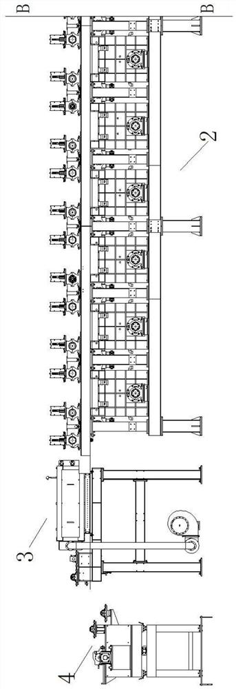
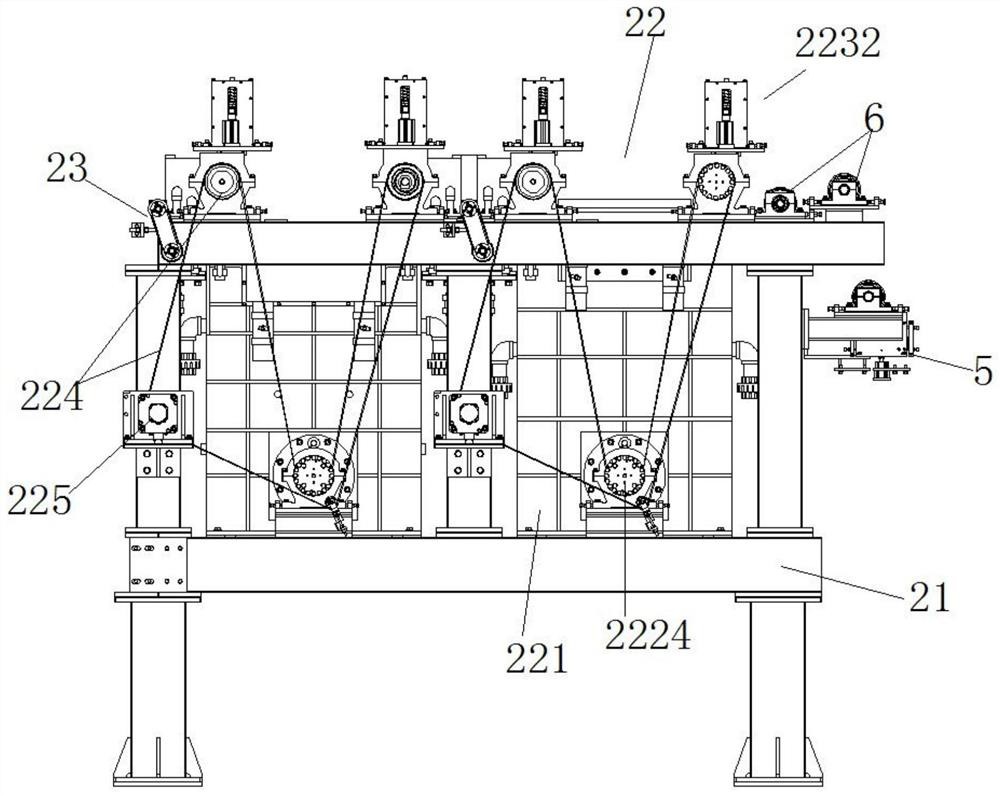
[0034] Such as Figure 1-11 As shown, the present invention discloses an electrolytic copper foil surface treatment machine, which is mainly composed of an uncoiling device 1, an intermediate treatment tank section 2, a drying box 3, a winding device 4 and a control device. The intermediate treatment tank section 2 Including: a frame 21, a plurality of processing devices 22 arranged on the frame 21, and a tension roller 232 mechanism 23 arranged between adjacent processing devices 22; the processing device 22 includes a processing tank 221, a conductive Device 222, water squeezing device 223, synchronous belt transmission mechanism 224, drive motor reducer 225 are formed, and described processing tank 221 is installed in frame 21, and the liquid roller 2213 in processing tank 221 stretches out processing tank 221 part and passes bearing The seat 2221 is fixed on the frame 21, the conductive device 222 is installed on the frame 21 on both sides above the treatment tank 221, the...


PUM


Abstract

The invention relates to an electrolytic copper foil surface processor. The electrolytic copper foil surface processor is mainly composed of an uncoiling device, an intermediate treatment groove section, a drying box, a coiling device and a control device, and the intermediate treatment groove section comprises a rack, a plurality of treatment devices arranged on the rack and tensioning roller mechanisms arranged between the adjacent treatment devices. Submerged rollers and conductive rollers are driven to rotate through magnetic force, it is guaranteed that tension of the multiple treatment devices is the same, and the production quality of copper foils is improved. The positions of anode plates are changed, the conveying positions of the copper foils are adjusted, the rough surfaces of the copper foils face the anode plates and make direct contact with the submerged rollers, the surfaces of the copper foils cannot be roughened through the conductive rollers, the smoothness of the surfaces of electroplated layers is improved, the electroplating efficiency is improved by arranging a partition plate between every two anode plates, liquid inlets are formed between the submerged rollers and the anode plates, so that the electroplating liquid between the anode plates and the copper foils can be supplemented more quickly, and the electroplating quality of the copper foils is guaranteed.

Description

technical field [0001] The invention relates to a surface treatment machine, in particular to an electrolytic copper foil surface treatment machine and its working method. Background technique [0002] The electrolytic copper foil surface treatment machine is mainly composed of an uncoiling device, an intermediate treatment tank section, a drying box, a winding device and a control device; the unwinder will discharge the copper foil to be processed, and the intermediate treatment tank Pickling-roughening first-curing first-roughening second-curing second-water washing-galvanizing-water washing-chrome plating-water washing first-water washing second treatment for copper foil, and the drying box dries the treated copper foil , the copper foil after drying is rewound through the winding machine; the surface treatment of electrolytic copper foil is an advanced treatment process commonly used in the production of finished electrolytic copper foil in the world at present; in the p...

Claims


Application Information

Patent Timeline
IPC IPC(8): C25D19/00C25D5/10C25D5/48C25D7/06C25D17/00C25D21/00C25D21/14F26B13/08F26B13/28F26B25/00B08B7/00
CPCB08B7/0028C25D5/10C25D5/48C25D7/0621C25D17/00C25D21/00C25D21/14F26B13/08F26B13/28F26B25/001
Inventor 李海涛云光义凌胜
Owner 洪田科技有限公司
Why Eureka
Try Eureka