
Hydraulic vibration damper, in particular for a vehicle chassis

A hydraulic shock absorber and chassis technology, which is applied in the direction of liquid shock absorber, shock absorber, spring/shock absorber functional characteristics, etc., can solve the problems of unfavorable check valve service life and wear, and adverse effects on comfort, etc. Achieving reduced noise levels, improved comfort, and reduced demand

Active Publication Date: 2019-11-15
THYSSENKRUPP BILSTEIN +1
View PDF15 Cites 0 Cited by
  • Summary
  • Abstract
  • Description
  • Claims
  • Application Information

AI Technical Summary

Problems solved by technology

This behavior has a detrimental effect on comfort during the life of the shock absorber, for example due to the high level of noise generated by the recoil of the valve disc, and is also detrimental to the service life and wear of the non-return valves

Method used


Image

  • Hydraulic vibration damper, in particular for a vehicle chassis
  • Hydraulic vibration damper, in particular for a vehicle chassis

Examples


Embodiment Construction

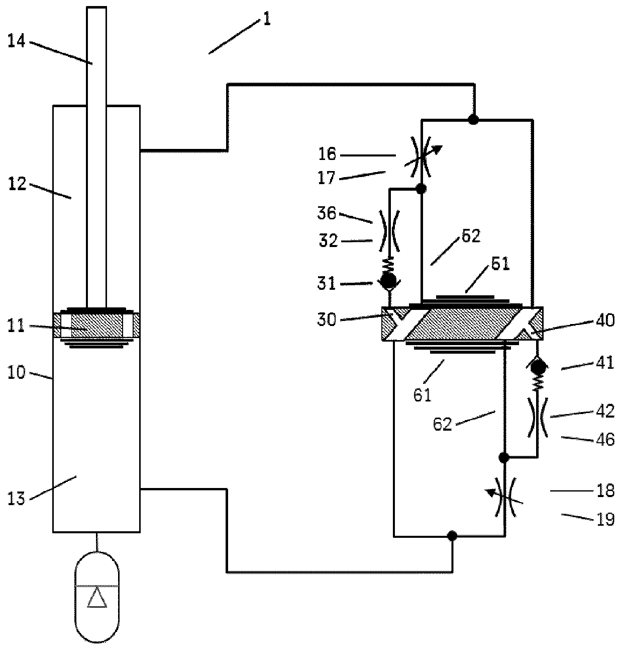
[0038] In the various figures, identical parts are always provided with the same reference numerals and will therefore generally also be referred to or mentioned only once in each case.

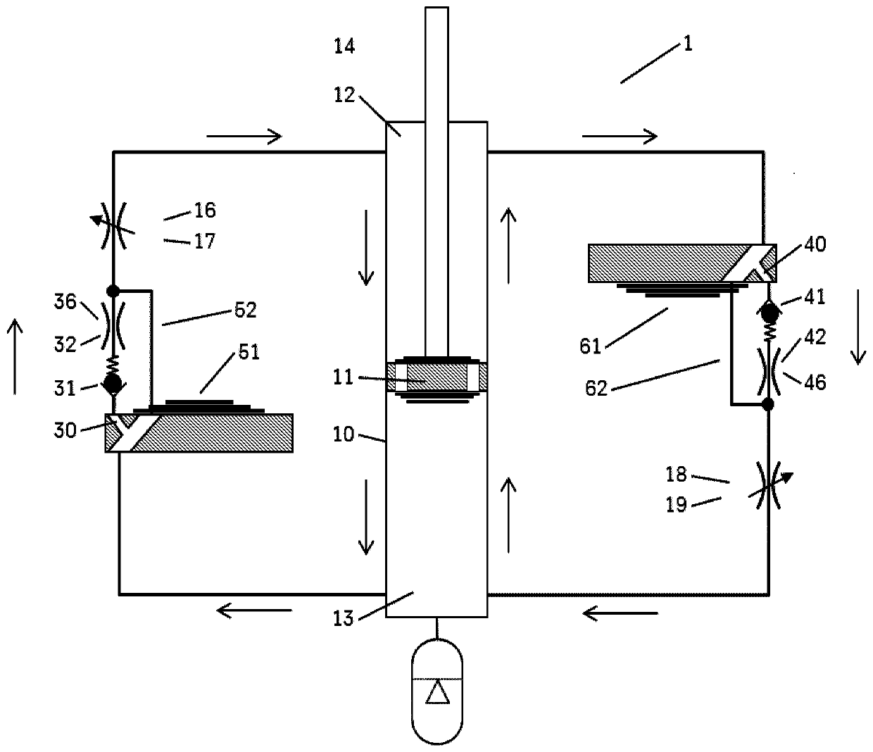
[0039] figure 1 A block diagram showing the hydraulic flow in the shock absorber 1 according to an exemplary embodiment of the present invention. Arrows pointing upwards indicate the direction of flow in the compression phase of the piston 11 , and arrows pointing downwards indicate the direction of flow in the rebound phase of the piston 11 . Piston 11 includes a piston rod 14 and divides cylinder 10 into a first working chamber 12 and a second working chamber 13 . Two sub-ducts 30, 40 of the bypass duct 20 are shown. Here, the sub-pipe 30 includes a check valve 31 connected in series and a throttle valve 32 connected in series as part of a throttle mechanism 36 with said check valve 31 . In this case, the blocking direction of the non-return valve 31 points to the side facing away from t...


PUM


Abstract

A hydraulic vibration damper (1), in particular for a vehicle chassis, comprising a cylinder tube (10) for accommodating a hydraulic fluid, a piston (11) which is movable axially within the cylinder tube (10) along a cylinder tube axis and which divides the cylinder tube into two working chambers (12, 13), a piston rod (14) which is oriented parallel to the cylinder tube axis and which is connected to the piston (11), wherein at least one valve assembly (51) for damping the piston movement in an actuating direction is arranged at a fluid leadthrough (52), wherein, in addition to the fluid leadthrough, between the two working chambers, there is provided a bypass channel (20) which comprises at least one secondary channel (30), wherein at least one valve arrangement with continuously adjustable damping force (16) is provided, which at least one valve arrangement regulates the throughflow through the fluid leadthrough (52) and through the secondary channel (30), characterized in that thesecondary channel (30) comprises at least one throttle mechanism (36) with at least one throttle (32) and comprises at least one check valve (31), wherein the throttle (32) and the check valve (31) ofthe secondary channel (30) are arranged in series with respect to one another.

Description

technical field [0001] The invention is based, for example, on shock absorbers with bypass ducts as used in vehicles. Background technique [0002] Such a shock absorber is known from document DE 10 2008 015 412 B4. In the case of the known shock absorber, a bypass pipe system consisting of two sub-pipes is used. For the rebound phase and the compression phase of the piston, a solenoid control valve is used in each case, by means of which the flow cross section is set for the respective flow direction. The damping force of the shock absorber can be set separately for the rebound phase and the compression phase via the control valve. Furthermore, for the shock absorber it is the case that during the compression phase and the rebound phase of the piston, only one of the sub-ducts flows in each case. In each case, the closing of the other sub-line is effected by a non-return valve, at least one of which is installed in each case for both flow directions. For each direction ...

Claims


Application Information

Patent Timeline
Patent Type & Authority Applications(China)
IPC IPC(8): F16F9/46F16F9/18
CPCF16F9/34F16F9/46F16F9/19B60G13/08B60G17/08B60G2202/24B60G2204/62B60G2206/41B60G2500/104B60G2500/114B60G2800/162F16F9/348F16F9/465F16F9/50F16F2222/12F16F2228/066F16F2234/02
Inventor 沃尔夫冈·哈默斯
Owner THYSSENKRUPP BILSTEIN
Learn More