A voltage adjustment circuit, a nonlinear dimming circuit and method for LED lighting
A voltage adjustment circuit, LED lighting technology, applied in electrical components and other directions, can solve problems such as being susceptible to external noise interference, PWM frequency stroboscopic, external noise interference, etc. the effect of interference
- Summary
- Abstract
- Description
- Claims
- Application Information
AI Technical Summary
Problems solved by technology
Method used
Image
Examples
Embodiment 1
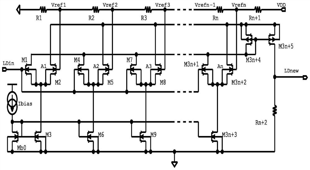
[0037] Please refer to figure 1 , this embodiment provides a voltage adjustment circuit, the voltage adjustment circuit is configured to match and set the circuit gain according to the value of the input voltage, and is used for non-linear adjustment of the input voltage for output;
[0038] The voltage adjustment circuit includes a summation current mirror circuit, a differential pair bias current mirror circuit, a reference voltage generation circuit, a current-voltage conversion circuit, and several mutually cascaded gain circuits;
[0039] In this embodiment, the gain circuit is a pair of NMOS transistors with a common source, and the drains of the NMOS transistors are respectively connected to the operating voltage and the current input terminal of the summation current mirror circuit, and the gate is respectively connected to the voltage input terminal and the reference voltage generation circuit;
[0040] The reference voltage generation circuit is composed of voltage d...
Embodiment 2
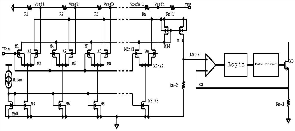
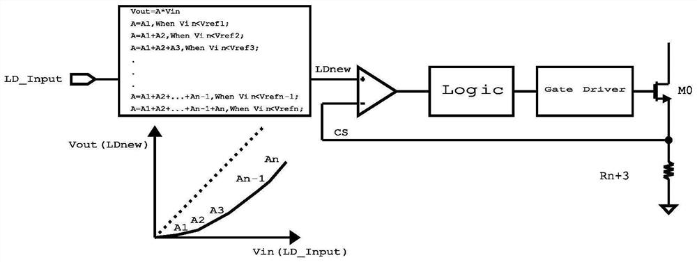
[0052] Please refer to figure 2 and image 3 , on the basis of Embodiment 1, this embodiment provides a non-linear dimming circuit for LED lighting, including sequentially cascaded comparator circuits, logic circuits, gate drive circuits, switch circuits and current detection circuits, and such as In the voltage adjustment circuit described in Embodiment 1, the voltage output end of the voltage adjustment circuit is connected to the non-inverting input end of the comparator circuit; the switch circuit in this embodiment adopts a high-power MOS switch M0, and the current detection circuit current detection resistor Rn +2, and the inverting input terminal of the comparator circuit is connected to the common terminal of the MOS switch M0 and the detection resistor Rn+2.
[0053] Please refer to Figure 4 For the existing linear dimming circuit, LD_Input is used to control the output signal to achieve the purpose of modulating the output LED current, thereby controlling the bri...
Embodiment 3
[0058] Please refer to image 3 , on the basis of embodiments 1 and 2, this embodiment provides a non-linear dimming method for LED lighting, including:
[0059] Collect the value range of the input voltage value, and divide the value range according to the design requirements;
[0060] determining the number of gain circuits according to the divided intervals and setting the gain of each gain circuit;
[0061] According to the divided intervals, determine the size of the reference voltage for each gain circuit to trigger access, and configure the reference voltage generation circuit;
[0062] Sequentially configure a summation current mirror circuit, a differential pair bias current mirror circuit, a current-voltage conversion circuit, and sequentially cascaded comparator circuits, logic circuits, and gate drive circuits;
[0063] Input voltage, perform voltage non-linear adjustment, including:
[0064] If Vin1 , then A=A1;
[0065] If Vref 1 ≤Vin2 , then A=A1+A2;
[00...
PUM
 Abstract
Description
Claims
Application Information
 - R&D
- Intellectual Property
- Life Sciences
- Materials
- Tech Scout
- Unparalleled Data Quality
- Higher Quality Content
- 60% Fewer Hallucinations
Browse by: Latest US Patents, China's latest patents, Technical Efficacy Thesaurus, Application Domain, Technology Topic, Popular Technical Reports.
© 2025 PatSnap. All rights reserved.Legal|Privacy policy|Modern Slavery Act Transparency Statement|Sitemap|About US| Contact US: help@patsnap.com


