
Miniature magneto-optical fiber switch

A fiber optic switch and miniature technology, applied in optics, nonlinear optics, instruments, etc., can solve the problems of large device volume, large polarization correlation and waveguide coupling loss, slow switching response speed, etc., and achieve ultra-small size and polarization correlation. The effect of low loss and low insertion loss

Pending Publication Date: 2019-11-15
ZHEJIANG UNIV
View PDF0 Cites 1 Cited by
  • Summary
  • Abstract
  • Description
  • Claims
  • Application Information

AI Technical Summary

Problems solved by technology

For example, the mechanical optical fiber switch is currently the most widely used optical fiber port switching device. It has very small insertion loss and crosstalk characteristics, but its switching time is limited to within milliseconds, and the device itself is bulky; other optical switches using MEMS, Mechanisms such as thermo-optical switch and liquid crystal optical switch technology, the switch response speed is relatively slow, generally in the order of milliseconds; the optical fiber switch speed realized by magneto-optical technology and acousto-optic technology can be tens of microseconds to hundreds of microseconds. Microseconds; while semiconductor electro-optic switching speed can reach nanoseconds, but there are defects such as polarization dependence and waveguide coupling loss.

Method used


Image

  • Miniature magneto-optical fiber switch
  • Miniature magneto-optical fiber switch
  • Miniature magneto-optical fiber switch

Examples


Embodiment Construction

[0036] In order to describe the present invention more specifically, the technical solutions of the present invention will be described in detail below in conjunction with the accompanying drawings and specific embodiments.

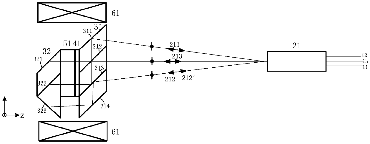
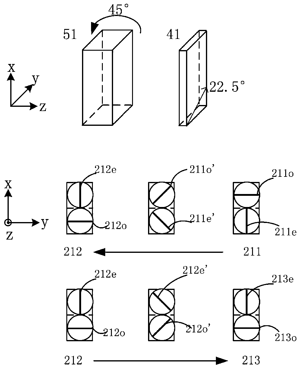
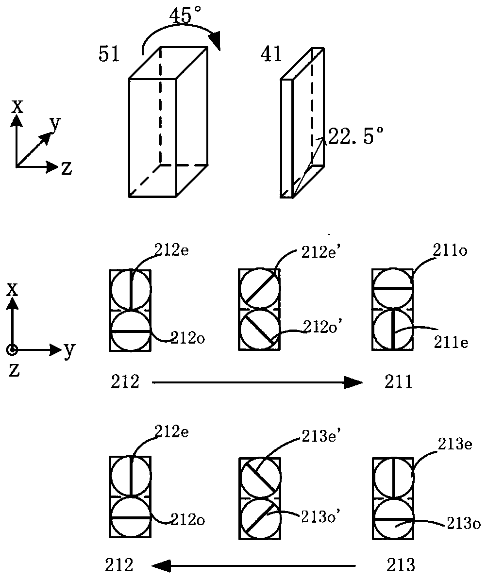
[0037] Such as figure 1 As shown, the miniaturized magneto-optical fiber switch of the present invention includes a three-fiber collimator 21, a first polarization beamsplitter prism 31, a wave plate 41, a magneto-optic crystal 51, a second polarization beamsplitter prism 32, and a coil 61; wherein, the first polarization beamsplitter The prism 31, the wave plate 41, the magneto-optic crystal 51, and the second polarizing beam splitter prism 32 are bonded and assembled through a micro-optical process to form the optical core of the magneto-optical switch. The first polarizing beamsplitter prism 31 in the optical core of the magneto-optical switch comprises a first total reflection surface 311, a polarization beamsplitting surface 312, a second total refle...


PUM


Abstract

The invention discloses a miniature magneto-optical fiber switch, consisting of a miniature three-fiber collimator, a miniature current coil and a miniature space light processing optical kernel. Theminiature fiber switch with a 1*2 structure and a 2*1 structure is realized by controlling the current direction of the current coil, and the input and output fibers of the miniature magneto-optical fiber switch are located on the same side. The scheme of the invention adopts the three-fiber collimator and the miniature space light processing optical kernel, realizes the micro-structured magneto-optical fiber switch which can simultaneously implement various switching working modes, and has the advantages of multiple working modes, simple structure, ultra-small size, low insertion loss, low polarization-dependent loss, single-sided fiber output, ultra-high channel switching repeatability and ultra-high lifetime.

Description

technical field [0001] The invention belongs to the technical field of optics and optical fiber communication, and in particular relates to a miniature magneto-optical optical fiber switch. Background technique [0002] A fiber optic switch is an optical device used in an optical system to switch between one or more input fiber ports and one or more output ports; a fiber optic switch is used in a fiber optic communication system to connect and disconnect The transmission optical channel for information loading provides functions such as network protection, link cross-connection, and add-drop multiplexing; optical fiber switches can also be used to make light sources generate pulsed optical signals, such as lasers, or use optical fiber switch modulation to load information or cut off optical fiber channels to realize its related functions. [0003] A simple type of fiber optic switch is a 1×2 fiber optic switch that provides optical switching between one input port and two o...

Claims


Application Information

Patent Timeline
IPC IPC(8): G02F1/09
CPCG02F1/09G02F1/313G02F1/095
Inventor 金晓峰陈辉龙
Owner ZHEJIANG UNIV
Learn More