
A kind of treatment method of hazardous solid waste oil sludge

A treatment method and technology of oil sludge, which is applied in the direction of pyrolysis treatment of sludge, petroleum industry, energy input, etc., can solve the problems of increasing solid or organic pollution, ineffective use of pyrolysis oil, treatment, etc., and simplifies the pretreatment process of oil sludge , easy to control, flexible operation

Active Publication Date: 2021-11-09
INST OF PROCESS ENG CHINESE ACAD OF SCI
View PDF18 Cites 0 Cited by
  • Summary
  • Abstract
  • Description
  • Claims
  • Application Information

AI Technical Summary

Problems solved by technology

In some pyrolysis processes, additional additives or catalysts are added to increase the pollution of solid or organic matter, and some pyrolysis slags are not further treated
Some of the obtained pyrolysis oil is re-incinerated, and the pyrolysis oil is not effectively used

Method used


Image

  • A kind of treatment method of hazardous solid waste oil sludge
  • A kind of treatment method of hazardous solid waste oil sludge
  • A kind of treatment method of hazardous solid waste oil sludge

Examples


Embodiment 1

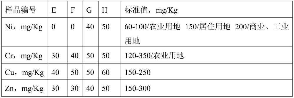
[0070] Weigh 43g of oil sludge 1 and place it in a pyrolyzer. According to the method of the present invention, a steam flow rate of 0.5L / min is introduced, and it is pyrolyzed at 550°C and 10kPa for 35min. The pyrolysis slag is sampled and analyzed, and then decarbonized by high-temperature combustion. Pyrolysis oil gas is collected and measured through condensation and separation. The obtained sample number is E, and the evaluation of the pyrolysis performance of the oil sludge is shown in Table 2. The correlation analysis of pyrolysis slag after combustion is shown in Table 3.

Embodiment 2

[0072] Weigh 52g of oil sludge 1 and place it in a pyrolyzer. According to the method of the present invention, a steam flow rate of 0.7L / min is introduced, and it is pyrolyzed at 600°C and 30kPa for 50min. The pyrolysis slag is sampled and analyzed, and then decarbonized by high-temperature combustion. Pyrolysis oil gas is collected and measured through condensation and separation. The obtained sample number is F, and the evaluation of the pyrolysis performance of the oil sludge is shown in Table 2. The correlation analysis of pyrolysis slag after combustion is shown in Table 3.

Embodiment 3

[0074] Weigh 46g of oil sludge 2 and place it in the pyrolyzer, feed steam flow rate 0.6L / min and water flow rate 0.1L / min according to the method of the present invention, and pyrolyze it at 550°C and 20kPa for 40min, and the pyrolysis slag is subjected to high temperature after sampling and analysis. Combustion to remove carbon. Pyrolysis oil gas is collected and measured through condensation and separation. The obtained sample number is G. The evaluation of the sludge pyrolysis performance is shown in Table 2. The correlation analysis of pyrolysis slag after combustion is shown in Table 3.


PUM


Abstract

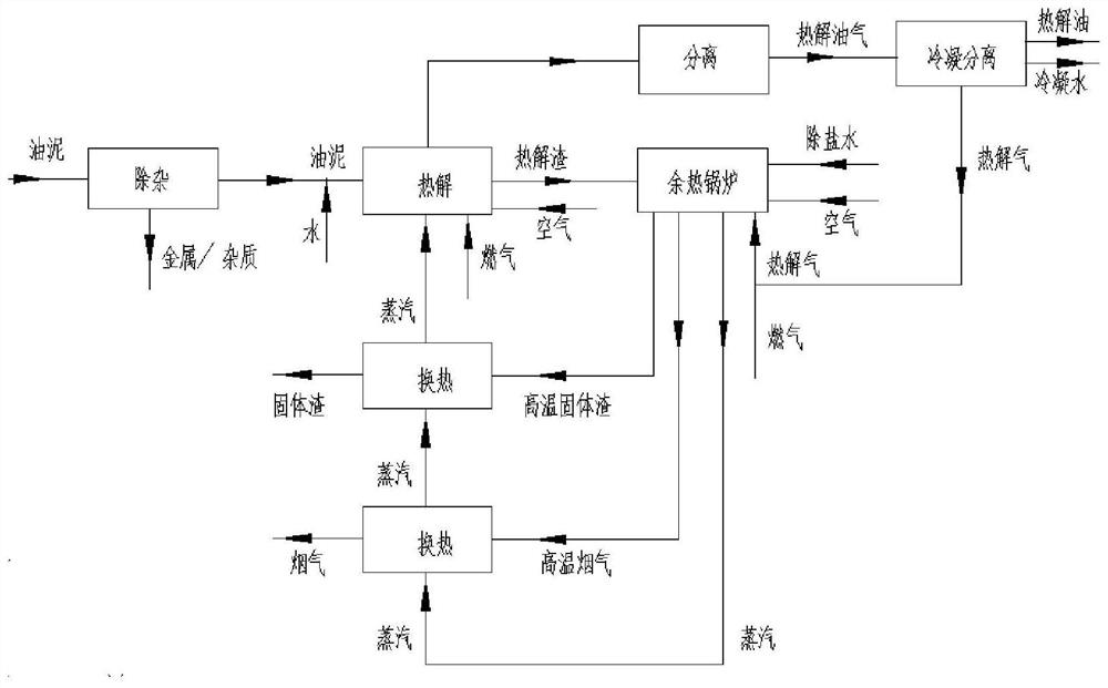
The invention relates to a method for treating dangerous solid waste oil sludge, which comprises the steps of: removing impurities; removing metals and bulk impurities. Pyrolysis: The sludge after removal of impurities enters the pyrolyzer, and is pyrolyzed under the action of steam to obtain the pyrolysis residue and pyrolysis oil and gas of carbon deposits. Separation: The pyrolysis oil and gas are separated by the condensation separation system to obtain pyrolysis oil and pyrolysis gas, and the pyrolysis oil products are recycled. Energy recovery: the pyrolysis gas and the pyrolysis slag of carbon deposits enter the waste heat boiler for combustion and heat supply, and the heat is used to generate steam for the pyrolysis process. The method for pyrolysis of oil sludge improves the yield of oil products in the pyrolysis process and reduces the carbon deposition amount of pyrolysis residues. The pyrolysis residue after the sludge is pyrolyzed and coke is incinerated, which avoids the generation of dioxins during the direct combustion of the sludge. The technological process rationally utilizes the gas and carbon deposits produced by pyrolysis, recovers high-quality oil products, and realizes the resource utilization of oil sludge.

Description

technical field [0001] The invention relates to a treatment method for hazardous solid waste oil sludge. More specifically, oil sludge is pyrolyzed under the action of steam to obtain oil and pyrolysis gas, carbon deposit pyrolysis slag and pyrolysis gas are further burned, and the waste heat is used to generate steam. A treatment method to realize resource utilization of hazardous solid waste oil sludge. Background technique [0002] The composition of oily sludge is mainly oil, mud and water. Oil contains a large amount of benzene series, phenols, anthracene, pyrene and other odorous toxic substances, if not handled properly, it will pollute water bodies and soil and cause environmental pollution. At present, oily sludge resource recycling technologies mainly include: solvent extraction technology, hot water washing treatment technology, biological treatment technology, profile control technology, oil sludge incineration, pyrolysis and other methods. [0003] Among them...

Claims


Application Information

Patent Timeline
Patent Type & Authority Patents(China)
IPC IPC(8): C02F11/10C10B53/00
CPCC02F11/10C10B53/00Y02W10/40Y02P20/129
Inventor 张美菊朱庆山
Owner INST OF PROCESS ENG CHINESE ACAD OF SCI
Learn More