Production method and production system for extracting oil from sludge

A production system and oil extraction technology, applied in the petroleum industry, by-product vaporization, pyrolysis treatment of sludge, etc., can solve the problems of low technical content, insufficient cracking, short construction period, etc. The effect of fast and uniform, not easy to stick and agglomerate

Active Publication Date: 2021-08-17
舟山麦哲伦环保科技有限公司
View PDF6 Cites 0 Cited by
  • Summary
  • Abstract
  • Description
  • Claims
  • Application Information

AI Technical Summary

Problems solved by technology

[0003] (1) Incineration technology: the treatment is thorough and can achieve reduction, but the cost of secondary pollution control is high, the waste is large, and it is not suitable for large-scale treatment;
[0004] (2) Solidified landfill technology: simple and easy to implement, fast in processing speed, and low in cost, but it cannot achieve reduction, and new environmental hazards may appear due to permanent land occupation;
[0005] (3) Hot washing-centrifugal dehydration technology: low technical content, simple operation and high efficiency, but the secondary pollution is serious, and the residue cannot meet the soil standard;
[0006] (4) Coking technology: the treatment is thorough and the effect is obvious, but the demand for production facilities is large;
[0007] (5) Ultrasonic technology: small investment and short construction period, but it is difficult to meet the needs of industrialization;
[0008] (6) Microbial technology: easy to operate, long-lasting effect, no secondary pollution, low treatment cost, but not suitable for waste with high oil content, and has high requirements on environmental conditions;
[0009] (7) Solvent extraction technology: easy to operate continuously, most of the crude oil can be recovered, and the solvent can be recycled, but the use process is long, the process is complicated, and the treatment cost is high
In this process, since the screw conveyor composed of hollow shaft and helical blades is used to transport the oil sludge inside the cracking device, due to the sticky characteristics of the oil sludge, the oil sludge is easy to stick into lumps during the process of pushing the oil sludge by the screw blades, resulting in poor heating. Uniformity, resulting in insufficient cracking, incomplete sludge harmless treatment, low oil recovery rate in sludge, etc.

Method used


Image

  • Production method and production system for extracting oil from sludge
  • Production method and production system for extracting oil from sludge
  • Production method and production system for extracting oil from sludge

Examples


Embodiment 1

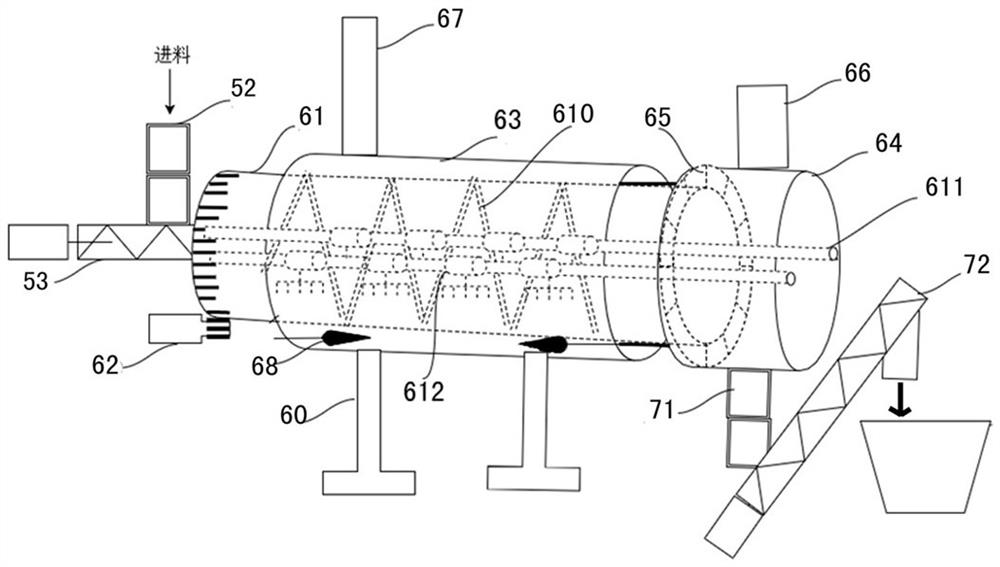
[0052] Figure 1 to Figure 14 Shown is an embodiment of the production system for extracting oil from sludge provided by the present invention.

[0053] see figure 1 , the production system includes a sludge pretreatment device, a feed device 5, a sludge pyrolysis device 6, a slag discharge device 7, and a gas condensation recovery device 9 arranged in sequence according to the sludge treatment process, wherein the sludge pretreatment device includes a raw material sludge crusher 1. Oil sludge three-phase separator 2 and oil sludge pool 3; gas condensation recovery device 9 includes a circulating water condensing device, an oil-water separation device 94, a recovery oil oil tank 4 and a catalytic burner, and the circulating water condensing device is an oil vapor condensing device 91, The closed-loop waterway system formed by the water air cooler 92, the water tank 93 and the negative pressure fan in series through the water pipeline; the oil sludge pyrolysis device 6 is a ro...

Embodiment 2

[0071] The present embodiment is the production method of extracting the oil in the oil sludge, and the flow process of the method is as follows:

[0072] 1. Pretreatment: The raw material sludge is crushed, and then the crushed sludge is subjected to three-phase separation pretreatment to obtain sludge and recovered oil. The recovered oil is recovered and stored in a recovered oil tank, and the sludge is sent to the sludge pool;

[0073] 2. Feeding: Use a grab bucket to send the sludge in the sludge pool to the feeding device. The feeding device adopts a closed feeding method to intermittently input the sludge into the sludge pyrolysis device. During the feeding process of the sludge pyrolysis device To ensure the airtightness of the feed;

[0074] 3. Pyrolysis treatment: The oil sludge pyrolysis device adopts the structure of the oil sludge pyrolysis device in Example 1, which is a rotary negative pressure oil sludge indirect heating device. The drum in working condition is...

Embodiment 3

[0079] The present embodiment is the production method of extracting the oil in the oil sludge, and its difference with embodiment 2 is:

[0080]The feeding device in step 2 adopts the structure of the feeding device in embodiment 1, realizes the intermittent feeding of sludge to the drum in a closed feeding manner, and ensures the airtightness of the feeding process of the drum. When starting to feed, the valve plates of the two hoppers in the feeding double hopper device are closed, and the feeding screw elevator intermittently and quantitatively conveys sludge to the upper hopper. After the quantitative sludge is filled with the upper hopper, the upper valve plate is opened, and the sludge enters the lower hopper After the hopper, close the upper valve plate, and then open the lower valve plate, the sludge is fed into the drum by the feeding screw conveyor, the feed amount of the drum sludge is controlled by controlling the speed of the feeding screw elevator, and the feedin...


PUM


Abstract

The invention discloses a production method and a production system for extracting oil from oil sludge. The oil sludge pyrolysis device includes a drum, the open end of the drum is connected with a fixed cylindrical discharge head, and the drum and the discharge head rotate. Seal fit; the inner wall of the drum is fixed with a spiral guide plate, the drum rotates, and the spiral guide plate pushes and lifts the sludge; the pyrolyzed oil vapor and residue are discharged from the discharge head; the decoking and crushing device in the drum includes parallel The fixed shaft on the axis of the drum, on the fixed shaft is provided with a plurality of de-coking claws at intervals along the axial direction, the handle ends of the de-coking claws can be rotatably sleeved on the fixed shaft, and the claw ends are elastically pressed against the inner wall of the drum by springs On the top, the rotation direction of the claw end under the action of the spring is opposite to that of the drum; the decoking claws grab the inner wall of the drum with the rotation of the drum, remove coking on the inner wall, and break up the sludge. The invention realizes continuous industrialized production of extracting oil from oil sludge, has high pyrolysis efficiency, complete oil sludge harmless treatment, and high oil recovery rate.

Description

technical field [0001] The invention belongs to the technical field of oily sludge treatment, and in particular relates to a device and method for treating oily sludge by pyrolysis and extracting oil therefrom. Background technique [0002] Oily sludge (hereinafter referred to as oil sludge) mainly comes from the cabins of oil tankers and various oil storage facilities. Substances such as sand heavy metal salts have complex components and belong to a relatively stable multiphase system. They are one of the important pollution sources causing pollution in the port area and have been included in the national hazardous waste list. Currently, the commonly used technologies for treating oily sludge are as follows: [0003] (1) Incineration technology: the treatment is thorough and can achieve reduction, but the cost of secondary pollution control is high, the waste is large, and it is not suitable for large-scale treatment; [0004] (2) Solidified landfill technology: simple an...

Claims


Application Information

Patent Timeline
Patent Type & Authority Patents(China)
IPC IPC(8): C02F11/10C10G1/00
CPCC02F11/10C10G1/00Y02W10/40
Inventor 虞皓元
Owner 舟山麦哲伦环保科技有限公司
Why Eureka
Try Eureka