Solid pollutant remover spraying device with flange-type inlet

A spraying device and removal agent technology, applied in liquid spraying devices, spraying devices, gas treatment, etc., can solve the problem of incomplete coverage of the flue flow surface, lower pollutant absorption rate\adsorption rate, and unsatisfactory particle diffusion effect and other issues, so as to improve the level of environmental governance, avoid the impact of pressure, and ensure the effect of contact

Pending Publication Date: 2019-11-15
BEIJING SPC ENVIRONMENT PROTECTION TECH
View PDF0 Cites 1 Cited by
  • Summary
  • Abstract
  • Description
  • Claims
  • Application Information

AI Technical Summary

Problems solved by technology

However, the existing adsorbent / absorbent injection device generally adopts a straight pipe to be directly inserted into the flue, and the adsorbent / absorbent outlet of the injection device adopts a single row of straight nozzles, and the particle diffusion effect of a single nozzle is not ideal. It cannot completely cover the flow surface of the flue gas. Under the pressure of the flue gas, the diffusion area of ​​the adsorbent\absorbent sprayed from the outlet will be reduced compared with that in the static state, so that the pollutants in the flue gas cannot be fully recovered. In contact with adsorbent\absorbent, pollutant absorption rate\adsorption rate decreases

Method used


Image

  • Solid pollutant remover spraying device with flange-type inlet
  • Solid pollutant remover spraying device with flange-type inlet
  • Solid pollutant remover spraying device with flange-type inlet

Examples


Embodiment Construction

[0028] In order to make the technical problems, technical solutions and advantages to be solved by the present invention clearer, the following will describe in detail with reference to the drawings and specific embodiments.

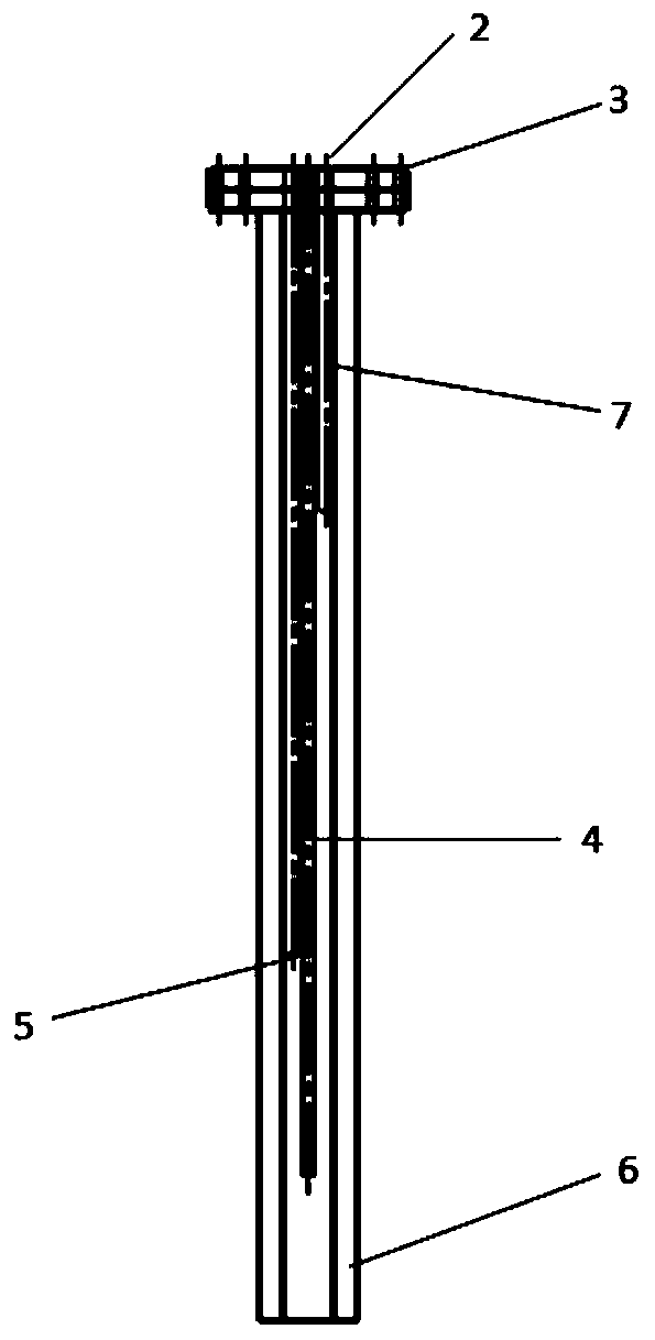
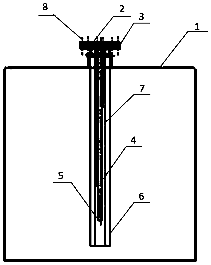
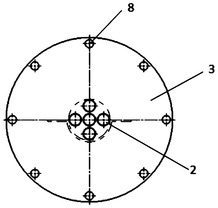
[0029] Such as Figure 1 ~ Figure 2 and Figure 5 As shown, the remover injection device of the present invention includes a flue 1, the flue gas circulates in the flue 1, the flue gas flows from front to back along the flue 1, and the remover spray gun 4 is set in the flue 1, The stripper spray gun 4 comprises the stripper inlet 2 of the upper end, the stripper spray gun flange plate 3 fixed by the bolt 8, the stripper outlet 5 arranged at the lower end of several quantity stripper spray guns 4 and the stripper outlet 5 which is welded on the stripper by the bracket. Remover deflector 6 except the nozzle 7 of agent spray gun 4, the length of remover deflector 6 perpendicular to flue 1 is (n+1) / of the length of the longest one in nozzle 7 n, n is the ...


PUM

PropertyMeasurementUnit
diameteraaaaaaaaaa

Abstract

The invention provides a solid pollutant remover spraying device with a flange-type inlet. The solid pollutant remover spraying device with the flange-type inlet comprises the remover inlet, a removerspray gun flange, remover spray guns, remover outlets and a remover guide board, wherein the remover inlet and the remover outlets are formed in the remover spray guns, the remover spray gun flange is arranged on the remover spray guns, the remover spray guns are provided with spray pipes with a number equal to or larger than 2, the remover guide board is welded to the spray guns through a support, and is longitudinally distributed along the spray guns, a cross section is in a shape of the Greek letter omega, moreover, by means of flat wing surfaces which extend from the remover guide board,the area of the remover guide board can be enlarged, the portion, located in a smoke contact position, on the lower reach of the remover guide board forms a low pressure area, thus turbulence of fluidis enhanced, effects of smoke are avoided, a spraying area of a remover is enlarged, thus the remover and the corresponding fluid are combined better, and the remover guide board is arranged below aninlet curved pipe, so that the spraying quantity of each spray gun is further uniformized.

Description

technical field [0001] The invention relates to the technical field of flue gas pollutant removal, in particular to a flange-type inlet pollutant solid removal agent injection device. Background technique [0002] There are many pollutants in modern industrial flue gas, such as coal-fired power plants, waste incineration, metal smelting, cement production and other industrial production enterprises will produce substances that pollute the atmosphere, mainly including SO 2 , SO 3 , NO x , HCl, heavy metals (represented by mercury), dioxins and other pollutants. [0003] Among them, acid gas is the most common pollutant in industrial flue gas, and the above-mentioned SO 2 , NO x , SO 3 , HCl as a representative, where SO 2 , NO x If the content is high, if it is not properly controlled, it will cause environmental pollution such as acid rain and photochemical smog; SO 3 As a pollutant present in a small amount in flue gas, its hazard is higher than that of SO 2 severa...

Claims


Application Information

Patent Timeline
Patent Type & Authority Applications(China)
IPC IPC(8): B01D53/83B01D53/06B05B7/04
CPCB01D53/06B01D53/83B01D2253/102B01D2258/0283B05B7/0416
Inventor 郝向宇许昌日史丽羽王玉山程俊峰刘英华
Owner BEIJING SPC ENVIRONMENT PROTECTION TECH
Why Eureka
Try Eureka