A waste combustion furnace with heat flow organization

A combustion furnace and waste technology, applied in the direction of combustion type, combustion method, incinerator, etc., can solve the problems of secondary pyrolysis carbon black that is difficult to burn out, impact, and excessive emissions, so as to avoid flue gas denitrification, ensure stable combustion, combustion stabilization effect

Active Publication Date: 2021-07-23
TONGJI UNIV +1
View PDF8 Cites 0 Cited by
  • Summary
  • Abstract
  • Description
  • Claims
  • Application Information

AI Technical Summary

Problems solved by technology

However, when industrial waste and some domestic waste with high calorific value are run on the existing pyrolysis gasification incinerator, there may be fluctuations and shocks caused by the instantaneous release of volatile matter. Violent combustion can lead to secondary cracking to produce carbon black that is difficult to burn out
At very high temperature, the oxygen supply is insufficient, and the charcoal produced in the pyrolysis stage of incineration will also be rapidly gasified to produce CO, resulting in excessive emissions
Therefore, although pyrolysis gasification incinerators are widely used on small garbage, there are still reliability problems in ensuring temperature combustion due to the influence of garbage components and moisture.

Method used


Image

  • A waste combustion furnace with heat flow organization
  • A waste combustion furnace with heat flow organization
  • A waste combustion furnace with heat flow organization

Examples


Embodiment 1

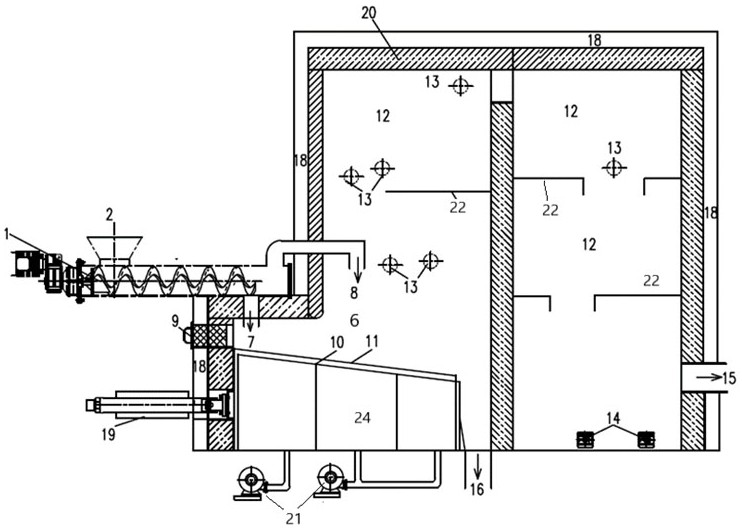
[0039] like figure 1 The illuminated waste combustion furnace having a heat flow tissue includes a cavity channel 1, a waste entrance hopper 2, an outer heat chamber 4, a combustion chamber 6, a pyrolysis carbon 7 transport channel, and the conveying passage of a combustion chamber 6, a pyrolysis carbon 7 Channel, furnace door 9, fixed furnace row 10, dynamic furnace row 11, two diverse chamber 12, air supply port 13, clear gray 14, flue gas outlet 15, slaushed port 16, insulation layer 18, drive mechanism 19, furnace wall 20, fan 21, the baffle wall 22 and the wind bun 24.

[0040] The cavity channel having a heat-flow tissue, a cavity channel 1 of transporting waste and a pyrolysis waste is selected from the group consisting of a shaft double helix or a sleeve of a sleeve of the outer heat chamber 4, and there is a waste in the inner side of the shaft double helix or the inner side of the rotor. The outer side has high temperature thermal flue gas, separated by metal walls in th...

Embodiment 2

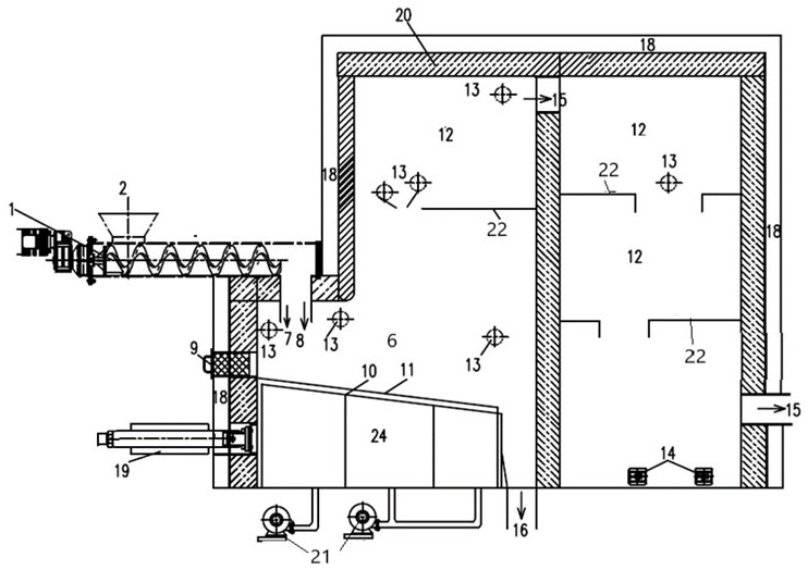
[0048] like figure 2 The illuminated waste combustion furnace is shown, including the transport of waste and waste pyrolysis, the waste entrance hopper 2, the outer heat chamber 4, the combustion chamber 6, the delivery channel of the pyroelectric carbon 7, and the conveying of the passage 8 Channel, furnace door 9, fixed furnace row 10, dynamic furnace row 11, two diverse chamber 12, air supply port 13, clear gray 14, flue gas outlet 15, slaushed port 16, insulation layer 18, drive mechanism 19, furnace wall 20, fan 21, the baffle wall 22 and the wind bun 24. The pyrolytic carbon 7 and the conveying channel of the volatilizing portion fall together on the stove.

[0049] The heat-fluvous waste combustion furnace, the transporting waste and the waste-free cavity channel 1 is selected from the group consisting of a shaft double helix or with any of the sleeve cartridges of the outer heat chamber 4, and the waste side is transported while being picked. The thermally desolation cavit...

Embodiment 3

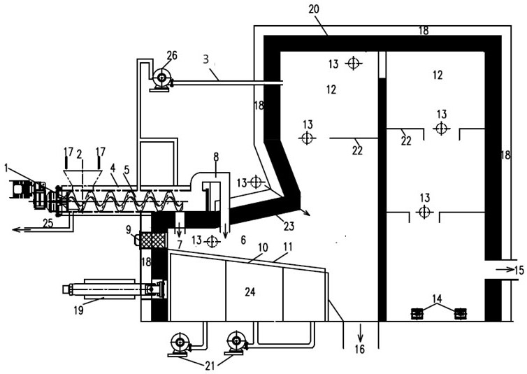
[0058] The waste residue of a paper mill, a water containing 35-38%, the heat value of 11.5-13 mJ / kg, the amount of treatment is 25 t / d, after breaking, image 3 The illustrated waste combustion furnace with thermal organisms, transporting waste and pyrolysis waste is selected from the prevision of spaced rotary kiln in the prior art, and the outer side of the rotary cylinder has an external heat of the waste heat. Room 4, the high temperature flue gas inlet 5 supplied from the high temperature flue gas circulating fan 26, the high temperature flue gas 3 is entered by high temperature flue gas inlet 5, and its cycle amount is guaranteed in the range of 500-650 ° C. The evaporation and export of moisture can be used in prior art, such as the collection technique of dry moisture in patented ZL201410305784.9. Wastes becomes two heat flows in the cavity passage 1 of transport waste and pyrolysis waste: pyrolyzed carbon 7 and volatilization 8. The thermal decomposer 7 is falling on ...


PUM


Abstract

The invention provides a waste combustion furnace with heat flow organization, which is composed of a waste pyrolysis chamber, a pyrolysis volatile component conveying passage and a combustion chamber, a pyrolysis charcoal conveying passage, a combustion chamber and a secondary combustion chamber. The delivery channel of the pyrolysis volatile matter is separated from the delivery channel of the pyrolysis charcoal; and the combustion chamber of the pyrolysis volatile matter and the pyrolysis charcoal are located in the same cavity, and the two supply oxygen for combustion respectively, and the charcoal The combustion of the volatile matter is the front position, and the combustion of the volatile matter is the rear position; or the delivery channel of the pyrolysis volatile matter and the delivery channel of the pyrolytic charcoal are integrated, and in the combustion chambers of the two, the two are respectively supplied with oxygen for combustion, The combustion of charcoal is the latter, and the combustion of volatiles is the former. The waste combustion furnace with heat flow organization provided by the present invention realizes dislocation combustion and mutual compensation of the two heat flows of volatile matter and pyrolytic carbon by dividing the waste into two heat flows of volatile matter and pyrolytic carbon and adjusting the air required for combustion , to cope with fluctuations in waste moisture and components, and to prevent the formation of NOx.

Description

Technical field [0001] The present invention belongs to the field of waste cleaning and resource, and more particularly to a waste combustion furnace with heat-flow tissue. Background technique [0002] In the prior art China, my country's domestic waste is mainly a large incinerator, and direct burning is achieved based on the stovetop technology or fluidized bed technology. In order to ensure that domestic waste is burned in the incinerator, use hot air supply, control furnace rapid speed, strengthening oxygen and disturbance, etc., but large urban waste incinerators corresponding to flue gas purification and fly ash disposal system cost is expensive, not only The proportion of investments is large, and the operation is higher, depending on high disposal, and power generation subsidies to achieve economic balance. The prior art small and medium-sized incineration technology is mainly used in the disposal of village and towns. In order to reduce the level of contaminants in the ...

Claims


Application Information

Patent Timeline
Patent Type & Authority Patents(China)
IPC IPC(8): F23G5/027F23G5/16F23G5/50
CPCF23G5/0276F23G5/16F23G5/50F23G2201/302F23G2201/303F23G2202/103
Inventor 陈德珍葛少恒胡雨燕何品晶刘会友
Owner TONGJI UNIV
Why Eureka
Try Eureka