Cooling structure of cylinder head

A technology of cooling structure and cylinder head, applied in the direction of cylinder head, cylinder, engine sealing device, etc., can solve the problem of poor cooling effect, and achieve the effect of improving cooling capacity, easy adjustment and good reliability

Pending Publication Date: 2019-11-12
GUANGXI YUCHAI MASCH CO LTD
View PDF1 Cites 0 Cited by
  • Summary
  • Abstract
  • Description
  • Claims
  • Application Information

AI Technical Summary

Problems solved by technology

[0005] The object of the present invention is to provide a cylinder head cooling structure, which aims to solve the problem of poor cooling effect in the high temperature area of ​​the cylinder head in the prior art

Method used


Image

  • Cooling structure of cylinder head

Examples


Embodiment Construction

[0018] In order to make the object, technical solution and advantages of the present invention clearer, the present invention will be further described in detail below through specific embodiments in conjunction with the accompanying drawings. It should be understood that the specific embodiments described here are only used to explain the present invention, not to limit the present invention.

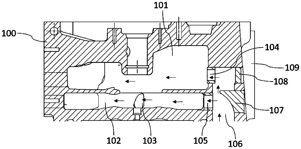
[0019] The invention provides a cylinder head cooling structure, such as figure 1 shown, including:

[0020] The main water channel 106, the first water jacket 101, the second water jacket 102, the nose bridge area 103, the first water inlet 104 and the second water inlet 105 arranged in the cylinder head 100; the main water channel 107 is used to obtain cooling water Enter;

[0021] The first water jacket 101 is separated from the second water jacket 102 by a partition, and the first water inlet 104 is arranged on the top of the upper water channel 107, and the first water jacket 10...


PUM


Abstract

The invention provides a cooling structure of a cylinder head. The cooling structure of cylinder head comprises a main water channel arranged in a cylinder head, a first water jacket, a second water jacket, a nose bridge area, a first water inlet hole, a second water inlet hole and a guide block. The first water jacket and the second water jacket are separated by a partition plate, the first waterinlet hole is formed in the top end of the main water channel, the first water jacket is communicated with the main water channel through the first water inlet hole, the second water inlet hole is arranged below the first water inlet hole, the second water jacket is communicated with the main water channel through the second water inlet hole, and the nose bridge area is arranged in the second water jacket. According to the cooling structure of the cylinder head, layered independent cooling can satisfy the cooling of each high-temperature area of the engine, and the layered independent coolingeffect can greatly improve the cooling capacity of the whole engine.

Description

technical field [0001] The invention belongs to the technical field of cylinder head cooling, and in particular relates to a cylinder head cooling structure. Background technique [0002] The cooling water flow scheme of the engine in the prior art is to send water to the upper part of the cylinder barrel first, and then flow out through the cylinder head, and there is no forced water flow in the lower part of the cylinder barrel. Cooling water with a lower temperature is sent from the front end of the cylinder to the water jacket on one side of the cylinder, and then the main water flow flows through the gap between the cylinders to the other side of the cylinder, and passes through the gap between the cylinder and the cylinder head. The water holes flow upward into the cylinder head, then flow through the high-temperature area near the center of each cylinder, and finally flow out through the outlet pipe of the cylinder head. [0003] For example, the Chinese invention pa...

Claims


Application Information

Patent Timeline
IPC IPC(8): F02F1/40F02F11/00
CPCF02F1/40F02F11/002
Inventor 黄豪林铁坚班智博覃文
Owner GUANGXI YUCHAI MASCH CO LTD
Why Eureka
Try Eureka