
Equivalent thermal network modeling method of hybrid excitation axial magnetic field flux switching motor

A technology of magnetic flux switching motor and equivalent thermal network, which is applied in the fields of electrical digital data processing, instrumentation, calculation, etc., can solve the problem that the temperature field distribution of the hybrid excitation axial magnetic field flux switching motor is inconsistent in the axial direction and cannot correctly reflect the motor. temperature rise, lack of detailed analysis and calculation, etc., to reduce the difficulty, increase the speed of calculation, and achieve the effect of accurate calculation

Active Publication Date: 2019-11-05
NANJING UNIV OF SCI & TECH
View PDF2 Cites 7 Cited by
  • Summary
  • Abstract
  • Description
  • Claims
  • Application Information

AI Technical Summary

Problems solved by technology

[0008] The existing literature lacks the refinement of the thermal network of the mixed excitation axial field flux switching motor and ignores the analysis and calculation of the contact thermal resistance of the contact parts of different materials, which affects the transfer of the motor heat source and the temperature field of the motor. Accurate calculation has a great influence, and the equivalent thermal network method in the existing literature mostly uses two-dimensional models, because for conventional motors, the use of two-dimensional equivalent thermal networks can better calculate the temperature field of the entire motor , however, the temperature field distribution of the hybrid excitation axial field flux switching motor is not consistent in the axial direction, and only using a two-dimensional equivalent thermal network cannot correctly reflect the temperature rise of the motor

Method used


Image

  • Equivalent thermal network modeling method of hybrid excitation axial magnetic field flux switching motor
  • Equivalent thermal network modeling method of hybrid excitation axial magnetic field flux switching motor
  • Equivalent thermal network modeling method of hybrid excitation axial magnetic field flux switching motor

Examples


Embodiment

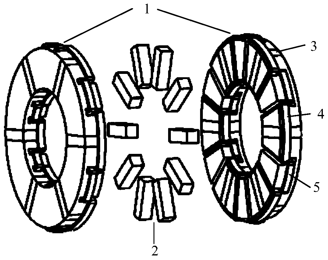
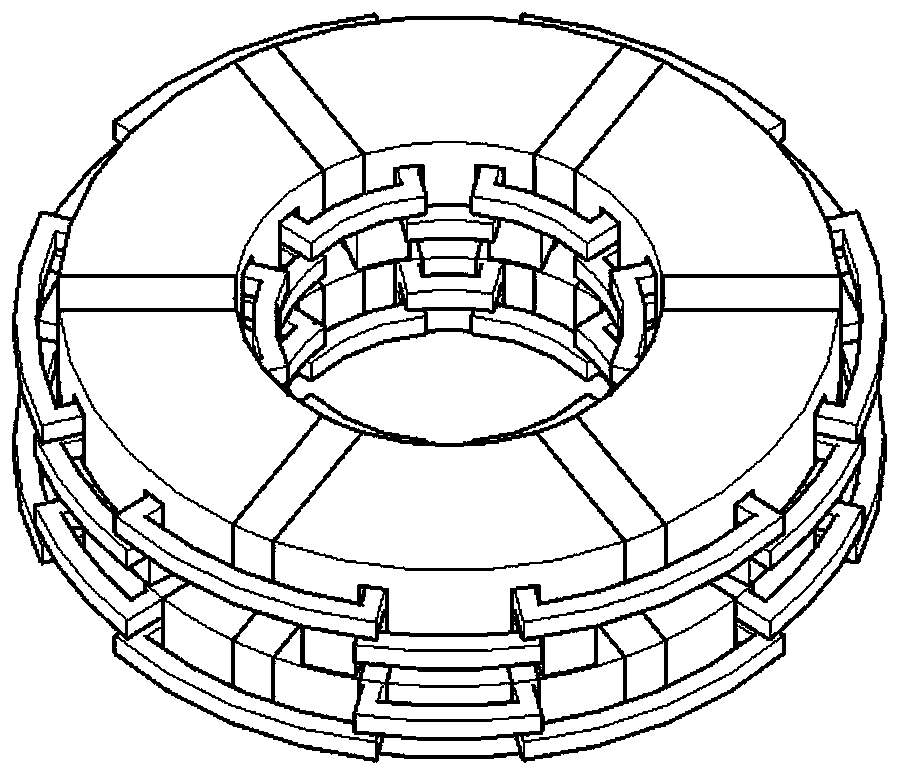
[0125] Combine figure 2 The motor used in the present invention is a 6 / 10-pole hybrid excitation axial flux switching motor. The motor adopts a double stator and single rotor structure, consisting of a stator 1, a rotor 2, a permanent magnet 3, an armature winding 4 and an excitation winding 5. Each stator 1 is composed of six E-type iron cores and six permanent magnets 3 alternately. The E-type iron core adopts parallel slots, and the permanent magnets 3 adopt parallel magnetization. The magnetization directions of adjacent permanent magnets 3 are opposite. The magnetization direction of the permanent magnet 3 on the side stator is also opposite; the armature winding 4 is wound on two adjacent stator teeth, and the field winding 5 is wound on the middle tooth of the E-shaped iron core; The group coils are connected in series to form a three-phase armature winding. The opposite in-phase armature coils on the stators on both sides are also connected in series; both the armature ...


PUM


Abstract

The invention discloses an equivalent thermal network modeling method of a hybrid excitation axial magnetic field flux switching motor. The method comprises the following steps: firstly, establishinga three-dimensional heat transfer model of a motor and an equivalent thermal network model of the motor; then, calculating the total heat productivity of the motor, distributing the heat to the heat source nodes, and calculating the heat transfer coefficient between the nodes according to the heat transfer empirical formula under different heat dissipation conditions; then equalizing the heat transfer between the nodes to the heat transfer between the simple geometries, and solving the equivalent thermal resistance between the nodes; and finally, establishing a mathematical model, and selecting a proper solving algorithm to solve the temperature rise of each node. The method reduces the difficulty of solving the temperature of the internal parts of the motor, is simple and quick, and is high in accuracy.

Description

Technical field [0001] The invention relates to the technical field of a modeling method for a motor thermal network, in particular to an equivalent thermal network modeling method for a hybrid excitation axial flux switching motor. Background technique [0002] In 2007, French scholar E. Hoang proposed a hybrid excitation flux switching (Hybrid Excitation Flux-switching, HEFS) motor based on the flux switching permanent magnet motor. This type of motor has good constant power speed regulation. The capacity and torque output capability have attracted widespread international attention. Compared with the radial field motor, the rotor core of the axial field motor has high utilization rate, high torque density, short axial length and compact structure, which is more suitable for occasions with high efficiency and low speed. [0003] Hybrid excitation axial flux switching motor combines the advantages of HEFS motor and axial motor, and has a broad development prospect in industrial f...

Claims


Application Information

Patent Timeline
IPC IPC(8): G06F17/50
Inventor 屠逸翔徐妲王绍帅
Owner NANJING UNIV OF SCI & TECH
Learn More