
Sleeve pipe for through-wall screw rod, and through-wall assembly applying sleeve pipe

A technology of wall-penetrating screw and sleeve, which is applied in the field of wall-penetrating screw sleeve and wall-penetrating components, which can solve problems such as trouble, low efficiency of sleeve installation, easy slipping of sleeve, etc.

Pending Publication Date: 2019-11-05
ZHEJIANG COMPRESSED FLUID TRANSMISSION ENG
View PDF11 Cites 1 Cited by
  • Summary
  • Abstract
  • Description
  • Claims
  • Application Information

AI Technical Summary

Problems solved by technology

[0004] In the above-mentioned use process, the building formwork system has the following problems: First, the sleeve may easily slip off the wall-through screw; When one end between the formwork and the second formwork is suspended, the wall-through screw sometimes sags due to its own weight. At this time, the sleeve will tilt downward and easily slip off the wall-through screw, especially when the second formwork has been erected, and the first When the formwork and the second formwork are both high, it is not easy to pick up the bushing that slipped between the first formwork and the second formwork. Sometimes it is necessary to remove the second formwork to pick up the sleeve, which is troublesome; When the new casing is installed, the installation efficiency of the casing is low; specifically, when the first formwork and the second formwork are installed in place and before the cement is poured, if it is found that the casing is missing, or considering the strength and safety, it is necessary to set the through-wall When screwing the screw (at this time, it is necessary to set a new through hole on the first formwork or the second formwork, and then put in a new sleeve and a new wall-through screw), it is necessary to disassemble the installed second formwork and make it A certain distance away from the first formwork to leave a space for operating the casing; repeat the above-mentioned use process of the building formwork system, that is, put the through-wall screw into the first through hole of the first formwork from the outside of the first formwork, and from the second Put the bushing on the wall-through screw on the inner side of the first formwork, reinstall the second formwork to a suitable position, and then pass the wall-through screw through the second through hole of the second formwork; it can be seen that the first formwork and the second formwork After the second formwork has been installed in place, if a new casing needs to be added, the second formwork needs to be installed and disassembled multiple times, the installation efficiency of the casing is low, and the construction cost is high; the third is that the casing cannot be reused; specifically, cement After being solidified into a wall, there is a negative pressure between the sleeve and the wall, which makes it difficult to remove the sleeve from the wall, so that the sleeve cannot be reused
The sleeves in the above two patents can be easily removed and reused, but neither of the above two patents solves the problem that the sleeve is easy to slip off the wall-through screw and the installation efficiency of the sleeve is low when adding a new sleeve

Method used


Image

  • Sleeve pipe for through-wall screw rod, and through-wall assembly applying sleeve pipe
  • Sleeve pipe for through-wall screw rod, and through-wall assembly applying sleeve pipe
  • Sleeve pipe for through-wall screw rod, and through-wall assembly applying sleeve pipe

Examples


Embodiment 1

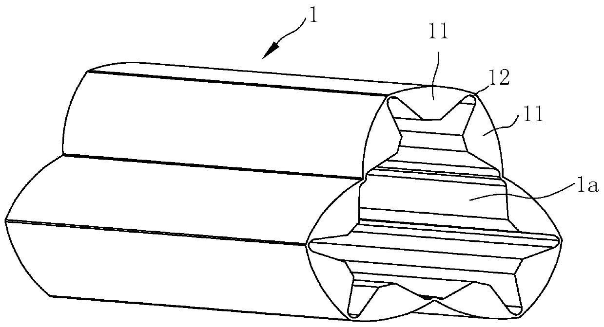
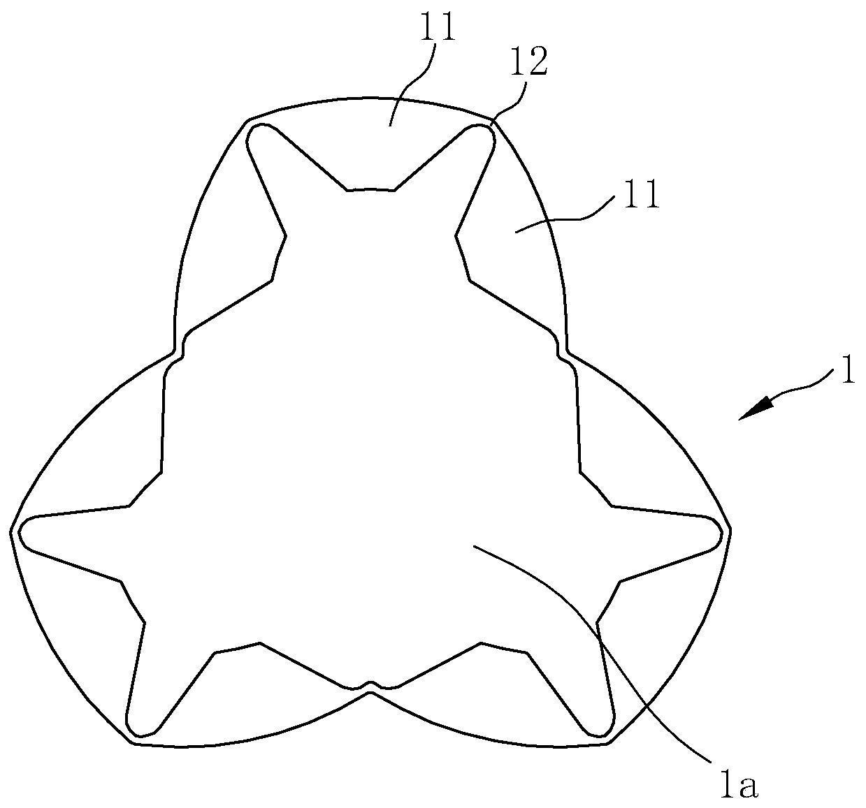
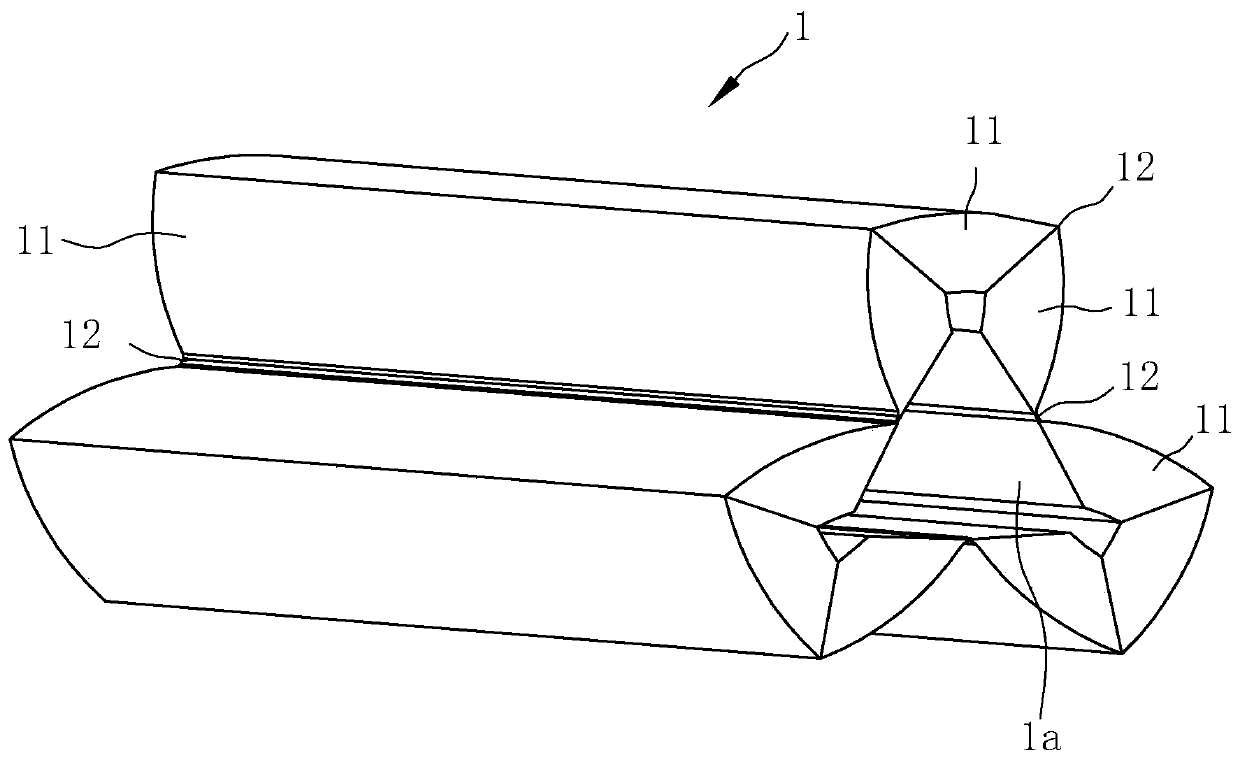
[0058] Such as Figure 1~6 Shown is a preferred embodiment of the bushing for the wall-penetrating screw according to the embodiment of the present invention. The casing for the wall-penetrating screw includes an integrally formed pipe body 1, which is provided with a perforation 1a extending axially through the pipe body 1, and the radial dimension of the pipe body 1 can be adjusted;

[0059] The tubular body 1 has a contracted state formed by shrinking radially inward after being compressed in a natural state. For example, the natural state of the sleeve in this embodiment can be figure 1 with figure 2 state in , the contracted state can be image 3 with Figure 4 state in Figure 5 with Image 6 The state in is the expansion state of the casing; in other embodiments, it can also be Figure 5 with Image 6 is the natural state of the casing, Figure 1 ~ Figure 4 Both are in the contracted state of the casing;

[0060] The pipe body 1 includes a connecting wall 11 a...


PUM


Abstract

The invention discloses a sleeve pipe for a through-wall screw rod. The sleeve pipe for the through-wall screw rod comprises a pipe body, wherein a through hole penetrating along the axial direction is formed in the pipe body; the radial size of the pipe body can be adjusted; and the pipe body comprises a connecting wall and an elastic thin wall. Therefore, a constructor can operate the sleeve pipe on the outer side of a first template, so that the occurrence of the phenomenon that the sleeve pipe slides off from the through-wall screw rod is reduced or avoided; and the sleeve pipe can be recycled. The invention further discloses a through-wall assembly applying the sleeve pipe for the through-wall screw rod. The through-wall assembly comprises the through-wall screw rod and a guiding piece, wherein the guiding piece can drive the radially contracted pipe body to move; and the through-wall screw rod can enable the sleeve pipe to be outwards expanded radially. The constructor can install the sleeve pipe after install all first templates and all second templates, so that the construction efficiency is high; and when a new sleeve pipe needs to be additionally arranged (for example, the sleeve pipe is missing or a new through-wall screw rod needs to be added), the times for disassembling and installing the second templates can be reduced, so that the installation efficiency of thesleeve pipe is improved.

Description

technical field [0001] The invention relates to the field of building formwork systems, in particular to a sleeve for a wall-penetrating screw and a wall-piercing assembly using the sleeve. Background technique [0002] During building construction, building formwork systems are often used. The building formwork system generally includes formwork, wall-through components, back corrugations, fastening nuts, etc. The wall-through components include wall-through screws and sleeves. For the convenience of description, two formworks are taken as examples. The two formworks are respectively recorded as No. A template and a second template, the first template and the second template are arranged oppositely, the first template is provided with a first through hole, the second template is provided with a second through hole, and the back flute is respectively arranged on the first template and the second template On the outside, the casing is arranged between the first formwork and ...

Claims


Application Information

Patent Timeline
Patent Type & Authority Applications(China)
IPC IPC(8): E04G17/065
CPCE04G17/0657Y02E30/30
Inventor 龚岳强
Owner ZHEJIANG COMPRESSED FLUID TRANSMISSION ENG
Learn More