
Target signal identification method based on rotor unmanned aerial vehicle-mounted equipment and ground equipment

A target signal and ground equipment technology, applied in the field of communication reconnaissance, can solve the problems that air communication reconnaissance equipment is not suitable for long-term reconnaissance, ground communication reconnaissance equipment has a short reconnaissance distance, and signal return time is long, so as to improve reconnaissance processing efficiency and identify The effect of high efficiency and recognition accuracy, and accurate target recognition results

Active Publication Date: 2019-11-01
36TH RES INST OF CETC
View PDF4 Cites 3 Cited by
  • Summary
  • Abstract
  • Description
  • Claims
  • Application Information

AI Technical Summary

Problems solved by technology

[0005] In view of the above analysis, the embodiment of the present invention aims to provide a target signal recognition method based on the rotorcraft on-board equipment and ground equipment, to solve the problem that the air communication reconnaissance equipment in the prior art is not suitable for long-term reconnaissance and signal return time. Longer, the ground communication reconnaissance equipment has a short reconnaissance distance and a long signal processing time

Method used


Image

  • Target signal identification method based on rotor unmanned aerial vehicle-mounted equipment and ground equipment
  • Target signal identification method based on rotor unmanned aerial vehicle-mounted equipment and ground equipment
  • Target signal identification method based on rotor unmanned aerial vehicle-mounted equipment and ground equipment

Examples


Embodiment 1

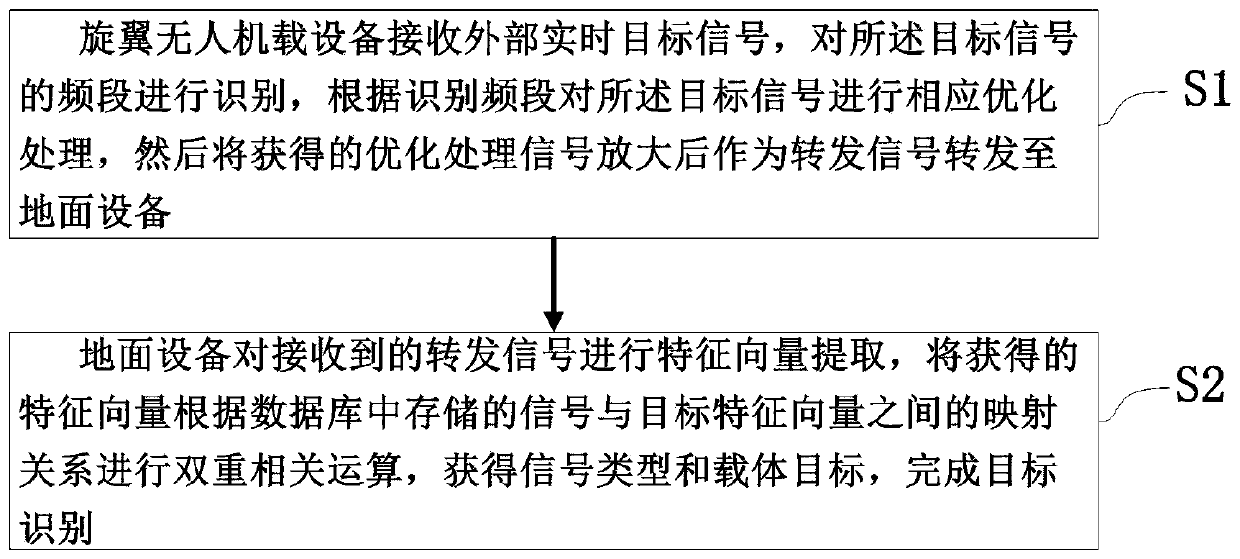
[0067] A specific embodiment of the present invention discloses a target signal recognition method based on rotorcraft equipment and ground equipment, such as figure 1 shown, including the following steps:

[0068] S1. The rotor UAV on-board equipment receives an external real-time target signal, identifies the frequency band of the target signal, performs corresponding optimization processing on the target signal according to the identified frequency band, and then amplifies the obtained optimized signal and forwards it as a forwarding signal to ground equipment;

[0069] S2. The ground equipment extracts the eigenvectors of the received forwarded signals, and performs double correlation calculations on the obtained eigenvectors according to the mapping relationship between the signals stored in the database and the target eigenvectors, to obtain the signal type and carrier target, and complete the target signal identify.

[0070] Optionally, the signal type is a frequency ...

Embodiment 2

[0074] Improvements are made on the basis of Embodiment 1. In step S1, identifying the frequency band of the target signal further includes the following steps:

[0075] S11. Transforming the external real-time target signal from the time threshold to the frequency domain by a fast Fourier transform method;

[0076] S12. Identify the frequency band of the external real-time target signal by using the obtained frequency domain result.

[0077] Preferably, the optimization processing of the target signal according to the identification frequency band described in step S1 further includes the following steps (two modes):

[0078] S13. The first mode is that when the frequency band of the target signal and the forwarding frequency band forwarded to the ground equipment belong to the same frequency band, the target signal is first converted to obtain the frequency band signal to be forwarded, and then the same-frequency signal cancellation method is used to eliminate the above-ment...

Embodiment 3

[0127] The present invention also provides a target signal identification system corresponding to the method described in Embodiment 1, such as figure 2 As shown, it includes rotorcraft airborne equipment and ground equipment. The rotor UAV on-board equipment can reach the sky near the target, and transmit the external real-time target signal sent by the other party to the ground equipment through WiFi.

[0128] The rotor UAV on-board equipment is used to receive external real-time target signals, identify the frequency band of the target signal, perform corresponding optimization processing on the target signal according to the identification frequency band, and then amplify the obtained optimized processing signal and forward it as a forwarding signal to ground equipment.

[0129] The ground equipment is used to extract the eigenvectors of the received forwarded signals, and perform double correlation calculations on the obtained eigenvectors according to the mapping relat...


PUM


Abstract

The invention relates to a target signal identification method based on rotor unmanned aerial vehicle-mounted equipment and ground equipment, belongs to the technical field of communication reconnaissance, and solves the problems that air communication reconnaissance equipment in the prior art is not suitable for long-time reconnaissance, the signal return time is relatively long, the reconnaissance distance of the ground communication reconnaissance equipment is short, and the signal processing time is long. The method comprises the following steps: rotor unmanned aerial vehicle equipment receiving an external real-time target signal, identifying the frequency band of the target signal, correspondingly optimizing the target signal according to the identified frequency band, amplifies theobtained optimized signal, and forwarding the amplified optimized signal to ground equipment as a forwarding signal; and the ground equipment performing feature vector extraction on the forwarded signal, performing dual correlation operation on the obtained feature vector according to the mapping relationship between the signal stored in the database and the target feature vector, and further obtaining a signal type and a carrier target to complete target signal identification. The method applies a dual correlation operation identification technology, and is high in target identification precision and reliable.

Description

technical field [0001] The invention relates to the technical field of communication reconnaissance, in particular to a method for identifying target signals based on rotorcraft-mounted equipment and ground equipment. Background technique [0002] The principle of communication reconnaissance technology is to obtain the law of the enemy's communication activities through the detection, identification and analysis of the communication signals of the non-cooperating party, and then grasp the state of the enemy's communication system and determine the location of the target radiation source. According to different loading platforms, communication reconnaissance equipment can be divided into different loading forms such as fixed station, vehicle-mounted, ship-borne and airborne. The working principle of each loading platform is basically the same, but different loading forms are selected according to the mission environment. [0003] At present, air communication reconnaissance ...

Claims


Application Information

Patent Timeline
IPC IPC(8): H04B7/185H04B1/40H04B1/04
CPCH04B1/04H04B1/40H04B7/18504H04B7/18506H04B2001/0408H04B2001/0416
Inventor 杨卓李敬德何伟
Owner 36TH RES INST OF CETC
Learn More