
Film forming liquid injection device for centrifugal film preparation

A liquid injection and film-forming technology, applied in the coating and other directions, can solve the problems of poor uniformity, strict requirements for the film-forming liquid and the danger of deflagration, and achieve the effect of reducing the shear rate and preventing it from directly falling into the film-forming area.

Pending Publication Date: 2019-11-01
深圳烯材科技有限公司
View PDF3 Cites 6 Cited by
  • Summary
  • Abstract
  • Description
  • Claims
  • Application Information

AI Technical Summary

Problems solved by technology

The Chinese invention patent application (publication number CN109177010A) proposes the basic structure of the equipment based on this technology to realize thin film preparation; at the same time, the equipment uses the atomization spraying process to deposit the film-forming liquid on the surface of the rotating substrate film, and can prepare continuous film with nanometer thickness. Membrane material, but there are problems such as poor uniformity, strict requirements on the film-forming liquid, and the risk of deflagration

Method used


Image

  • Film forming liquid injection device for centrifugal film preparation
  • Film forming liquid injection device for centrifugal film preparation
  • Film forming liquid injection device for centrifugal film preparation

Examples


Embodiment 1

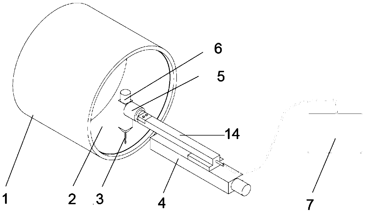
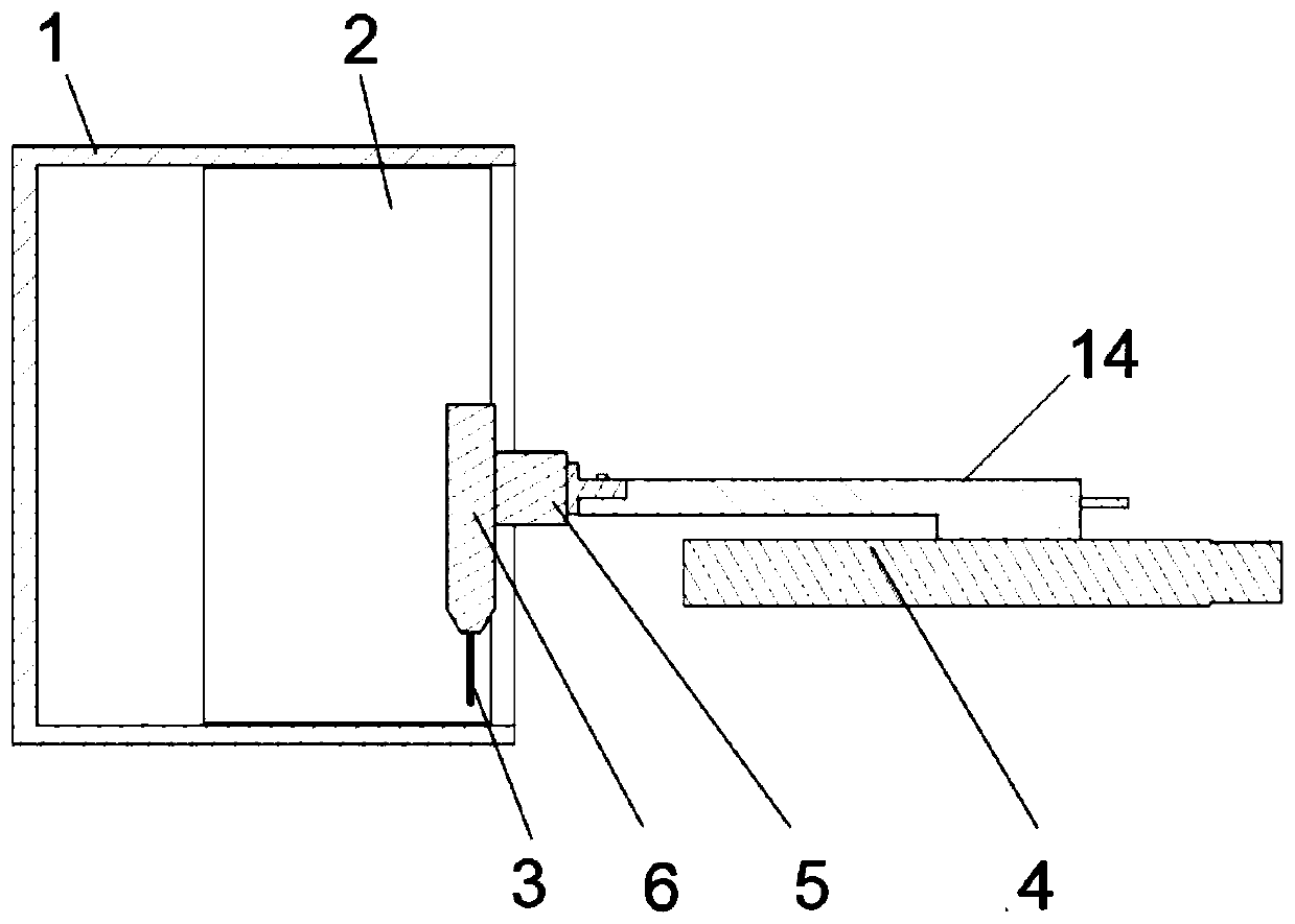
[0037] As shown in Figure 1 (a)-(b), in this embodiment, the basic structure of a simple film-forming liquid needle injection system includes: rotating drum 1, film-forming substrate 2, needle 3 (stainless steel needle), needle Moving device 4 (electric slide table) along the rotating axis of the drum, needle injection angle adjustment device 5 (reduced motor), needle telescopic device 6 (electric telescopic table), liquid booster pump 7, etc. Among them, the length of the stainless steel needle head is 50mm, the inner diameter is 300μm, and the outer diameter is 2mm; Sliding rod 14, sliding rod 14 is slidingly matched with the needle moving device 4 along the axis of rotation of the drum, and the length of sliding rod 14 is 210 mm; the needle injection angle adjustment device 5 is equipped with a deceleration stepping motor, and one end thereof is installed on the sliding rod 1 14 tail end, the other end of the needle injection angle adjustment device 5 is equipped with a nee...

Embodiment 2

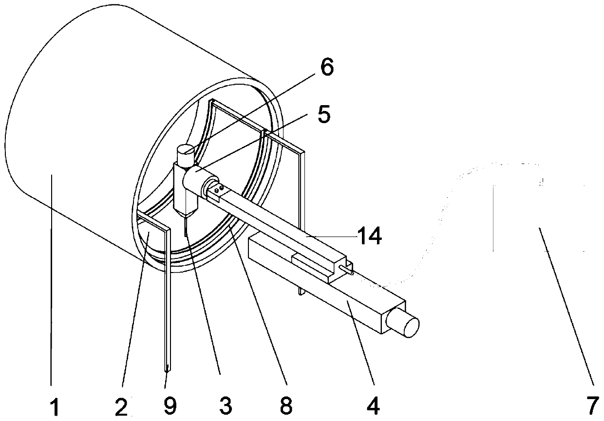
[0041] As shown in Figure 2(a)-(b), in this embodiment, a basic structure of a film-forming liquid needle injection system with a fixed residual liquid collection tank includes: a rotating drum 1, a film-forming substrate 2, a needle 3, Needle moving device 4 along the drum rotation axis, needle injection angle adjustment device 5, needle retractable device 6, liquid booster pump 7, fixed raffinate collection tank 8, fixed raffinate collection tank bracket 9, etc. Among them, the length of the stainless steel needle head is 50mm, the inner diameter is 300μm, and the outer diameter is 2mm; Sliding rod 14, sliding rod 14 is slidingly matched with the needle moving device 4 along the axis of rotation of the drum, and the length of sliding rod 14 is 210 mm; the needle injection angle adjustment device 5 is equipped with a deceleration stepping motor, and one end thereof is installed on the sliding rod 1 14 tail end, the other end of the needle injection angle adjustment device 5 i...

Embodiment 3

[0046] As shown in Figure 3(a)-(b), in this embodiment, a basic structure of a film-forming liquid needle injection system with a movable residual liquid collection tank includes: a rotating drum 1, a film-forming substrate 2, and a needle 3 , Needle head moving device 4 along the drum rotation axis, needle head injection angle adjustment device 5, needle head retractable device 6, liquid booster pump 7, movable residual liquid collection tank 10, collection tank moving device 11, etc.; wherein, the length of the stainless steel needle head is 50mm , with an inner diameter of 300 μm and an outer diameter of 2 mm; the needle head moving device 4 along the axis of rotation of the drum is a ball screw moving slide table with a width of 40 mm and a stroke of 150 mm; Rod one 14 is in sliding fit with the needle moving device 4 along the axis of rotation of the drum, and the length of the slide rod one 14 is 210mm; the needle injection angle adjustment device 5 is equipped with a dec...


PUM

PropertyMeasurementUnit
Lengthaaaaaaaaaa
Lengthaaaaaaaaaa
Lengthaaaaaaaaaa

Abstract

The invention relates to the field of thin film materials and device manufacturing, in particular to a film forming liquid injection device for centrifugal film preparation equipment. The device comprises a rotating drum, a film forming base body, a needle head, a device for moving the needle head in the direction of a rotating axis of the drum, a needle injection angle adjusting device, a needlehead stretching and retracting device and a film forming liquid pressurization assembly, the film forming base body is arranged on the inner surface of the rotating drum, a sliding rod I is arranged on the device for moving the needle head in the direction of the rotating axis of the drum, the sliding rod I is in sliding fit with the device for moving the needle head in the direction of the rotating axis of the drum, one end of the needle injection angle adjusting device is arranged at the tail end of the sliding rod I, the needle head stretching and retracting device is arranged at the otherend of the needle head injection angle adjusting device, a needle head is arranged on the needle head stretching and retracting device, and the needle head is connected with the film forming liquid pressurization assembly through a pipeline. The film forming liquid injection device is mainly used for injecting the film forming liquid of different substances into the surface of the rotating base body in the form of a liquid column so as to realize accurate control and preparation of a thin film structure.

Description

technical field [0001] The invention relates to the field of thin film materials and device manufacturing, in particular to a film-forming liquid injection device for centrifugal film-making equipment. The device is mainly used to inject film-forming liquids of different substances into the surface of a rotating base in the form of a liquid column. Realize the precise control preparation of thin film structure. Background technique [0002] Flexible large-area uniform nano-film materials can be widely used in technical fields such as optoelectronic devices, energy storage devices, protective functional coatings, catalytic synthesis, composite materials, etc., and the efficient control of preparation of nano-scale thickness film materials with uniform thickness is the key to realizing the above-mentioned The key process basis of the application. At present, the commonly used nano-thickness thin film material preparation technologies in industry mainly include evaporation, ma...

Claims


Application Information

Patent Timeline
IPC IPC(8): B29C41/04B29C41/36
CPCB29C41/04B29C41/36
Inventor 裴嵩峰韦覃伟任文才成会明
Owner 深圳烯材科技有限公司
Learn More