
Industrial boiler flue gas dehumidifying desulphurization denitration system and method

A desulfurization and denitrification, industrial boiler technology, applied in separation methods, chemical instruments and methods, agriculture, etc., can solve problems such as insufficient water resistance and sulfur resistance, and achieve the effects of improving effective service life, simple process, and low energy consumption

Pending Publication Date: 2019-11-01
HUANENG POWER INTERNATIONAL +1
View PDF9 Cites 5 Cited by
  • Summary
  • Abstract
  • Description
  • Claims
  • Application Information

AI Technical Summary

Problems solved by technology

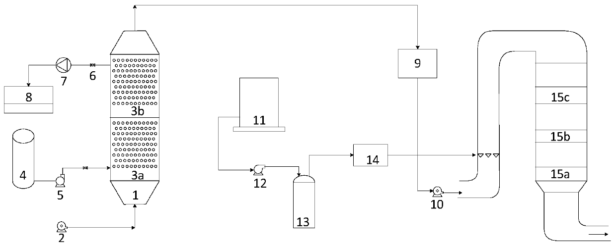
[0005] Aiming at the problem of insufficient water resistance and sulfur resistance of low-temperature denitrification catalysts in the prior art, the present invention provides a system and method for dehumidification, desulfurization and denitrification of flue gas from industrial boilers. The design is reasonable, and it can be combined with dehumidification, desulfurization and denitration. No harmful substances enter the environment, improving the effective service life of low-temperature SCR catalysts

Method used


Image

  • Industrial boiler flue gas dehumidifying desulphurization denitration system and method

Examples


Embodiment 1

[0044] 1) The flue gas is transported to the dehumidification and desulfurization tower 1 through the booster fan 2, and the flue gas is dehumidified and desulfurized by a hollow fiber membrane absorber formed by connecting two hollow fiber membranes in series. The mass concentration of the absorption liquid is 0.5%, The temperature is 70°C, the gas-liquid ratio is 75:1, and the vacuum degree inside the tube side of the fiber membrane absorber is 0.06MPa.

[0045] 2) The dehumidified and desulfurized flue gas enters the flue gas heater to be heated to 100°C, and then enters the denitrification tower through the induced draft fan.

[0046] 3) The flue gas at a temperature of 100°C enters the low-temperature denitrification tower for low-temperature denitrification treatment. The low-temperature denitrification catalyst is a low-temperature SCR with anatase-type nano-titanium dioxide as the carrier and cerium and vanadium metal oxides as active components. Catalyst, the molar ra...

Embodiment 2

[0049] 1) The flue gas is transported to the dehumidification and desulfurization tower 1 through the booster fan 2, and the flue gas is dehumidified and desulfurized by a hollow fiber membrane absorber formed by connecting two hollow fiber membranes in series. The mass concentration of the absorption liquid is 0.8%, The temperature is 90°C, the gas-liquid ratio is 100:1, and the vacuum inside the tube side of the fiber membrane absorber is 0.1MPa.

[0050] 2) The dehumidified and desulfurized flue gas enters the flue gas heater to be heated to 140°C, and then enters the denitrification tower through the induced draft fan.

[0051] 3) The flue gas at a temperature of 140°C enters the low-temperature denitrification tower for low-temperature denitrification treatment. The low-temperature denitrification catalyst is a low-temperature SCR with anatase-type nano-titanium dioxide as the carrier and cerium and vanadium metal oxides as active components. Catalyst, the molar ratio of ...

Embodiment 3

[0054] 1) The flue gas is transported to the dehumidification and desulfurization tower 1 through the booster fan 2, and the flue gas is dehumidified and desulfurized by a hollow fiber membrane absorber formed by connecting two hollow fiber membranes in series. The mass concentration of the absorption liquid is 0.6%, The temperature is 80°C, the gas-liquid ratio is 90:1, and the vacuum degree inside the tube side of the fiber membrane absorber is 0.08MPa.

[0055] 2) The dehumidified and desulfurized flue gas enters the flue gas heater to be heated to 180°C, and then enters the denitrification tower through the induced draft fan.

[0056] 3) The flue gas at a temperature of 140°C enters the low-temperature denitrification tower for low-temperature denitrification treatment. The low-temperature denitrification catalyst is a low-temperature SCR with anatase-type nano-titanium dioxide as the carrier and cerium and vanadium metal oxides as active components. Catalyst, the molar ra...


PUM


Abstract

The invention discloses an industrial boiler flue gas dehumidifying desulphurization denitration system and a method. The industrial boiler flue gas dehumidifying desulphurization denitration system comprises a dehumidifying desulphurization system, a flue gas heater, and a low temperature denitration system which are connected successively; the dehumidifying desulphurization system comprises a dehumidifying desulphurization tower, a supercharging blower fan, and a hollow fiber film absorber; the bottom of the dehumidifying desulphurization tower is provided with a flue gas inlet connected with the supercharging blower fan, the top is provided with a flue gas outlet, and the middle part is provided with the hollow fiber film absorber used for absorbing sulfur dioxide and water vapour; an input end of the hollow fiber film absorber is connected with an adsorption liquid supply unit, and an output end is connected with an adsorption liquid regeneration unit; an inlet of the flue gas heater is connected with a flue gas outlet on the top of the dehumidifying desulphurization tower; the low temperature denitration system comprises a denitration tower, an ammonium hydroxide supply unit,and a plurality of low temperature SCR catalyst units; a flue gas inlet on the bottom of the denitration tower is connected with an outlet of the flue gas heater through a blower fan; the ammonium hydroxide supply unit is connected with an ammonia spray grating arranged in the denitration tower; and the plurality of low temperature SCR catalyst units are arranged in the denitration tower successively.

Description

technical field [0001] The invention relates to the technical field of industrial boiler flue gas purification, in particular to an industrial boiler flue gas dehumidification, desulfurization and denitrification system and method. Background technique [0002] In my country, coal-fired industrial boilers are widely used in various industrial productions. They consume about 400 million tons of standard coal each year, accounting for about a quarter of the country's total coal consumption, and produce a large amount of sulfur dioxide and nitrogen oxides. and other pollutants. With the increasingly severe environmental protection situation, the treatment of industrial boiler flue gas is becoming more and more stringent. [0003] However, due to the low exhaust gas temperature of industrial boilers, generally only 120-140 °C, the means suitable for purifying industrial boiler flue gas are still relatively scarce. Among them, the low-temperature selective catalytic redox SCR fl...

Claims


Application Information

Patent Timeline
IPC IPC(8): B01D53/86B01D53/56C05C3/00C01C1/24
CPCB01D53/8625B01D53/22C05F9/02C05C3/00C01C1/24B01D2251/2062B01D2258/0283B01D2255/20707B01D2255/20723B01D2255/2065Y02E50/30
Inventor 郭中旭程广文杨嵩杨成龙赵瀚辰
Owner HUANENG POWER INTERNATIONAL
Learn More