
Patsnap Eureka
For R&D, Patsnap Eureka makes reading and utilizing patents & technical documents easy.
Patsnap Eureka AIR
Designed for self-driven R&D workflows. Generate viable solutions, solve complex R&D challenges, empower your innovation with AI.

Patsnap Eureka Materials
Designed for material experts only. Revolutionize your material R&D, from search, analyze, to developing new materials.

TechResearch
Generate reliable direction feasibility study reports for your R&D in just a few steps.

TechSeek
Discover and master advanced knowledge NOW. Basics, ideas, possibilities, all at once.

TechMind
As an expert in R&D Theories, TechMind can generates customized viable solutions instantly.

TechRisk
Analyze your overall solution with one click, know your potential R&D risks in advance.

TechMonitor
Get weekly tech updates, stay abreast of the latest tech innovations and key insights.
System for recycling industrial waste gas waste heat by means of heat transfer oil
A technology for industrial waste gas and heat transfer oil, applied in the field of waste gas waste heat recovery, can solve the problems of waste of resources, affecting the climate and environment, and achieve the effect of good applicability
- Summary
- Abstract
- Description
- Claims
- Application Information
AI Technical Summary
Problems solved by technology
Method used
Image

Examples
Embodiment 1
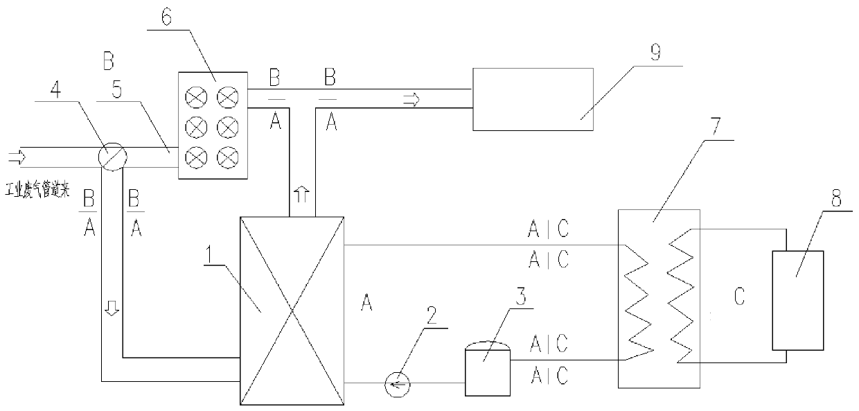
[0022] One of the specific implementations of a system for recovering waste heat from industrial waste gas by using heat transfer oil of the present invention, as figure 1 As shown, the industrial exhaust gas waste heat system includes a three-way valve 4 connected to the industrial exhaust gas source pipeline, one of the outlets of the three-way valve 4 communicates with the air cooler 6 through the bypass flue 5, and the air cooler 6 is connected to the ultra-low flue gas The discharge system 9 is connected; the other outlet of the three-way valve 4 is connected with the flue gas inlet of the heating module through the exhaust gas inlet flue.
[0023] In this embodiment, the heating module includes a heat collector 1 communicated with the three-way valve 4, and the heat collector 1 is connected to the industrial waste gas source pipeline and the ultra-low emission system 9 through the waste gas inlet flue and the waste gas outlet flue respectively. , the heat exchanger in th...
Embodiment 2
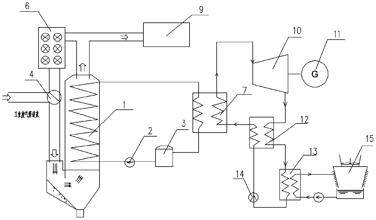
[0028] The second specific embodiment of a system for recovering waste heat from industrial waste gas by utilizing heat transfer oil of the present application, see figure 2 , the main technical solution of this embodiment is the same as that of Embodiment 1, and the features not explained in this embodiment are explained in Embodiment 1, and will not be repeated here. The difference between this embodiment and Embodiment 1 is that the other outlet of the three-way valve 4 communicates with the flue gas inlet of the power generation module through the exhaust gas inlet flue.
[0029] In this embodiment, the power generation module includes a heat collector 1 communicated with a three-way valve 4, and the heat collector 1 passes through the waste gas inlet flue and the waste gas outlet flue respectively to the industrial waste gas source pipeline and the flue gas ultra-low emission system 9, The heat exchanger in the heat collector 1 is sequentially connected to the heat trans...
Embodiment 3
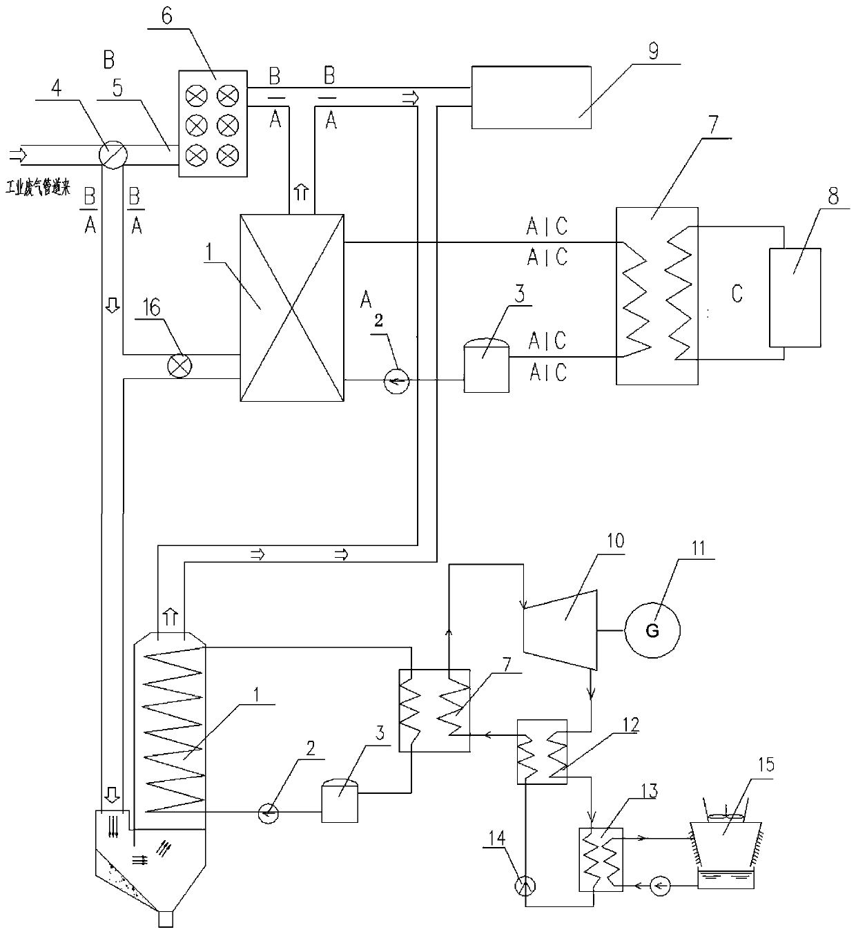
[0034] The third specific embodiment of a system for recovering waste heat from industrial waste gas by utilizing heat transfer oil of the present application, see image 3 , the main technical solution of this embodiment is the same as that of Embodiment 1, and the features not explained in this embodiment are explained in Embodiment 1, and will not be repeated here. The difference between this embodiment and Embodiment 1 is that the other outlet of the three-way valve 4 communicates with the flue gas inlet of the heating module and the flue gas inlet of the power generation module respectively through the exhaust gas inlet flue, and the three-way valve 4 is connected with the heating module. There is a flue gas valve 16 between the modules, through which the exhaust gas inlet flue is controlled to communicate with the flue gas inlet of the heating module. When there is a demand for heating, the flue gas valve 16 can be opened to start the heating module. In Embodiment 3, the...
PUM
 Abstract
Description
Claims
Application Information
 - R&D Engineer
- R&D Manager
- IP Professional
- Industry Leading Data Capabilities
- Powerful AI technology
- Patent DNA Extraction
Browse by: Latest US Patents, China's latest patents, Technical Efficacy Thesaurus, Application Domain, Technology Topic, Popular Technical Reports.
© 2024 PatSnap. All rights reserved.Legal|Privacy policy|Modern Slavery Act Transparency Statement|Sitemap|About US| Contact US: help@patsnap.com