Control system and control method of high-temperature valve with cooling function
A control system and high-temperature valve technology, applied in valve heating/cooling devices, valve lift, heat preservation, etc., can solve problems such as difficulty in resisting valve stem fatigue stress, affecting the accuracy of test results, and affecting the safety of test components, etc., to achieve Better cooling effect, lower temperature, effective temperature control
- Summary
- Abstract
- Description
- Claims
- Application Information
AI Technical Summary
Problems solved by technology
Method used
Image


Examples
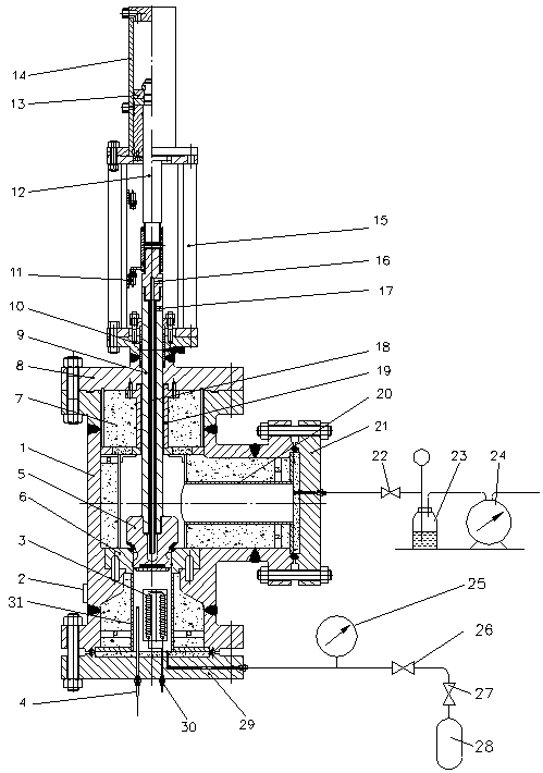
Embodiment 1
[0043] A control system for a high temperature valve with cooling function, such as figure 1 Shown: When the thermal valve is in a closed state, the components that are in direct or indirect contact with the stored high-temperature and high-pressure gas need to have sufficient mechanical strength, heat resistance, and heat insulation design. For example, the moving parts composed of the valve core 5 and the valve stem 9, the lower end of the valve core 5 generally needs to be equipped with a heat insulation block, and the outside is covered with a heat insulation coating; the valve stem 9 is generally hollow, and a valve stem is inserted in the center of the inner cavity to cool Pipe 18, when the hot valve is closed, cooling water is introduced from the water inlet 16 of the cooling pipe at the top of the valve stem 9, delivered to the valve core 5 through the valve stem cooling pipe 18 and cooled, and then discharged from the valve stem through the water outlet 17 of the cooli...
Embodiment 2
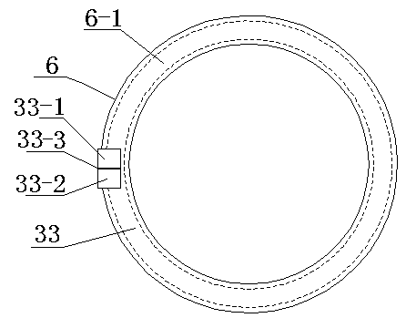
[0046] The invention provides a control system for a high temperature valve with cooling function, as attached figure 2 As shown, the cooling water channel 33 in the valve seat is completely contained in the single metal in the valve seat 6 .
[0047] The cooling water channel 33 in the valve seat is an annular closed area formed by wrapping the valve seat 6 and the valve seat water channel cover 6-1, as figure 2shown. The extended pipeline of the cooling water channel passes through the valve body 2 and has two interfaces with the outside world, namely: the cooling water passes through the valve body inlet channel 33-1 and the cooling water passes through the valve body outlet channel 33-2, and the cooling water passes through the valve body The inlet channel 33-1 is isolated from the cooling water outlet channel 33-2 through the valve body by a cooling water partition 33-3, and is closely arranged on one side of the valve seat, such as image 3 As shown; the cooling wate...
Embodiment 3
[0053] The present invention provides a control system for a high temperature valve with cooling function. The cooling water channel 34 in the valve body is completely contained in the single metal in the valve body 1 .
[0054] The cooling water channel 34 in the valve body is an annular closed section formed by wrapping the valve body 1 and the valve body water channel cover 1-1. The valve body water passage cover 1-1 and the valve seat 6 are closely fitted together. The cooling water channel is directly opened on the valve body 1 and connected with the outside world. Two interfaces are provided, namely: the cooling water inlet channel 34-1 and the cooling water outlet channel 34-2, and the cooling water inlet channel 34-1 and the cooling water channel. The water outlet channels 34-2 are separated by the cooling water partition 8-3, and are arranged close to the side of the valve seat; the cooling water flows in from the cooling water inlet channel 34-1, and after passing th...
PUM
 Abstract
Description
Claims
Application Information
 - R&D
- Intellectual Property
- Life Sciences
- Materials
- Tech Scout
- Unparalleled Data Quality
- Higher Quality Content
- 60% Fewer Hallucinations
Browse by: Latest US Patents, China's latest patents, Technical Efficacy Thesaurus, Application Domain, Technology Topic, Popular Technical Reports.
© 2025 PatSnap. All rights reserved.Legal|Privacy policy|Modern Slavery Act Transparency Statement|Sitemap|About US| Contact US: help@patsnap.com