Transmission mode electrochemical in-situ optical testing device

An optical testing and electrochemical technology, which is used in measurement devices, color/spectral property measurement, material analysis by optical means, etc., to achieve the effect of being easy to use and easy to assemble.

Pending Publication Date: 2019-10-22
南杰智汇(深圳)科技有限公司
View PDF2 Cites 1 Cited by
  • Summary
  • Abstract
  • Description
  • Claims
  • Application Information

AI Technical Summary

Problems solved by technology

To sum up, at present, the in-situ test devices for electrode materials are mainly concentrated in the reflection mode, and the in-situ test devices for the transmission mode are still missing. Therefore, there is an urgent need for a device that can accurately control the charging and discharging process, is easy to use, and can be repeated. The device with high reliability and stable performance conducts in-situ optical / neutron diffraction tests on electrode materials under electrochemical conditions in transmission mode

Method used


Image

  • Transmission mode electrochemical in-situ optical testing device
  • Transmission mode electrochemical in-situ optical testing device
  • Transmission mode electrochemical in-situ optical testing device

Examples


Embodiment 1

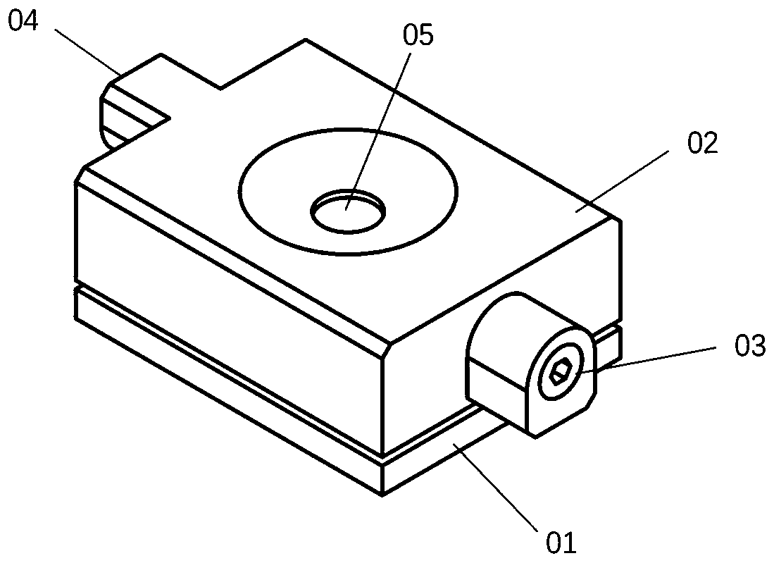
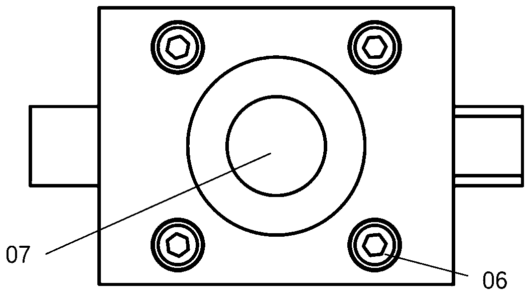
[0023] like figure 1 and figure 2 As shown, the test device involved in the present invention is composed of a base 01 and a main body 02. The main body 02 of the test box has electrode interfaces 03, 04 on both sides, and both interfaces have cylindrical or hexagonal column grooves inside, which are used to communicate with other Equipped with banana plugs for connection, banana plugs and external electrochemical workstation connection for precise control of current and voltage. like image 3 and Figure 4 As shown, a window 05 is opened on the top of the main body 02, and a window 07 is opened on the base, so that photons / neutrons can pass therethrough and used to collect test signals in transmission mode. like Figure 5 As shown, the various components of the device involved in the present invention are sealed by a sealing ring. The material to be tested is fixed between the electrode fixing plates 09 and 10 ( Image 6 , Figure 7 ), put it into the sealed test cavi...

Embodiment 2

[0026] Two gas channels can be opened at both ends of the device of the present invention, and the in-situ transmission mode research is carried out on the charging and discharging process of the tested material under a specific atmosphere. When in use, install the device and open the gas inlet and outlet as described in Example 1.

Embodiment 3

[0028] The device of the invention can provide a protective environment for materials sensitive to air or moisture, and is suitable for long-time transmission mode optical research on materials under non-electrochemical conditions. For use, the device can be installed as described in Example 1.


PUM


Abstract

The invention discloses a transmission mode electrochemical in-situ optical testing device and belongs to the field of material testing equipment and research. According to the device, in-situ opticaltesting can be performed an electrode material under a transmission mode in an electrochemical charging and discharging process, wherein optical testing involves testing of visible light of differentwavebands, laser testing, X-ray testing, synchronous radiation testing and neutron diffraction testing. The device disclosed by the invention is of a closed structure, is suitable for the measurementof a material sensitive to air and moisture, such as the electrode material of a battery; a positive pole fixing sheet and a negative pole fixing sheet are designed to fix a material to be tested, and therefore, the repeatability of testing is improved; electrode interfaces are adopted; the material can be electrochemically regulated in a testing process; an electrode can be in large-area contactwith the electrode material, so that the resistance of the device is reduced; two ends of the device are provided with observation windows, a passage is arranged at the middle of the device so as toallow light to pass through. The device has the advantages of convenience in assembling and disassembling and the like. The device disclosed by the invention can also be used in a reflection mode, andcan test electrode materials at two sides separately.

Description

technical field [0001] The invention relates to the field of auxiliary equipment for in-situ optical testing of electrode materials in an electrochemical process, in particular to in-situ optical testing of electrode materials for lithium ion batteries, including sodium ions and potassium ions, and electrode materials of alkaline earth metal batteries . The device can perform in-situ optical tests on electrode materials in transmission mode during electrochemical charging and discharging, including visible light, laser and X-rays in different wavelength bands, as well as synchrotron radiation and neutron diffraction tests. Background technique [0002] With the advancement of materials science, various optical characterization methods are constantly updated, providing a complex and diverse platform for people to further understand the properties of materials. In the field of electrochemistry, especially when rechargeable and dischargeable batteries have become a research ho...

Claims


Application Information

Patent Timeline
IPC IPC(8): G01N21/25G01N21/01G01N23/207
CPCG01N21/25G01N21/01G01N23/2073G01N2223/056
Inventor 邹健莉曹鲁杰
Owner 南杰智汇(深圳)科技有限公司
Why Eureka
Try Eureka