Fast preparation device and preparation method for rock direct-tension sample
A technology for tensile samples and preparation devices, which is applied in the field of rock mechanics tests, and can solve the problems of insufficient sample accuracy, eccentric tension, and high cost
- Summary
- Abstract
- Description
- Claims
- Application Information
AI Technical Summary
Problems solved by technology
Method used
Image
Examples
Embodiment 1
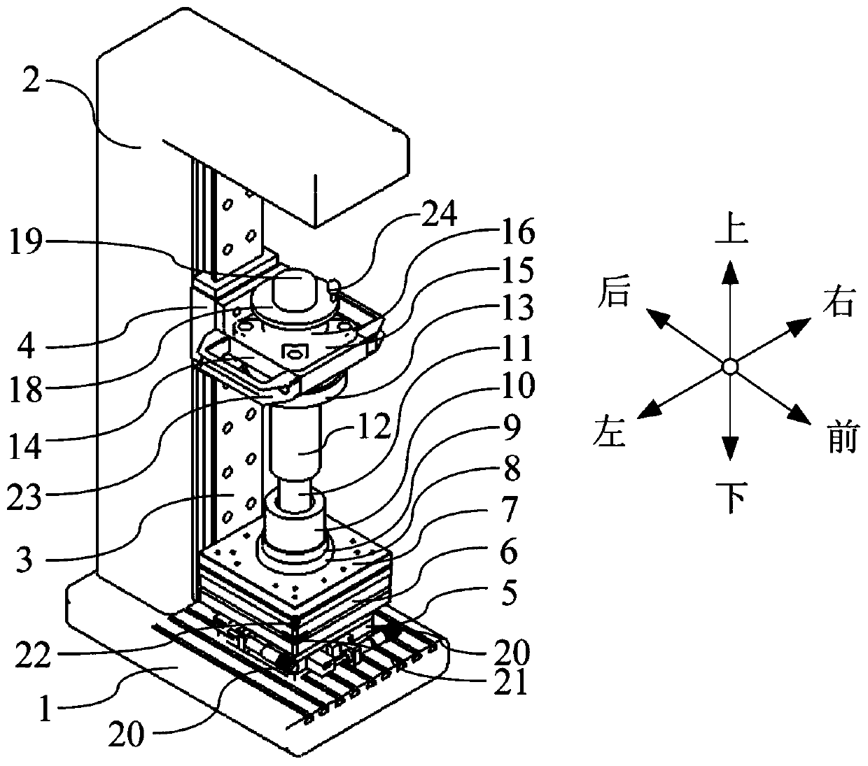
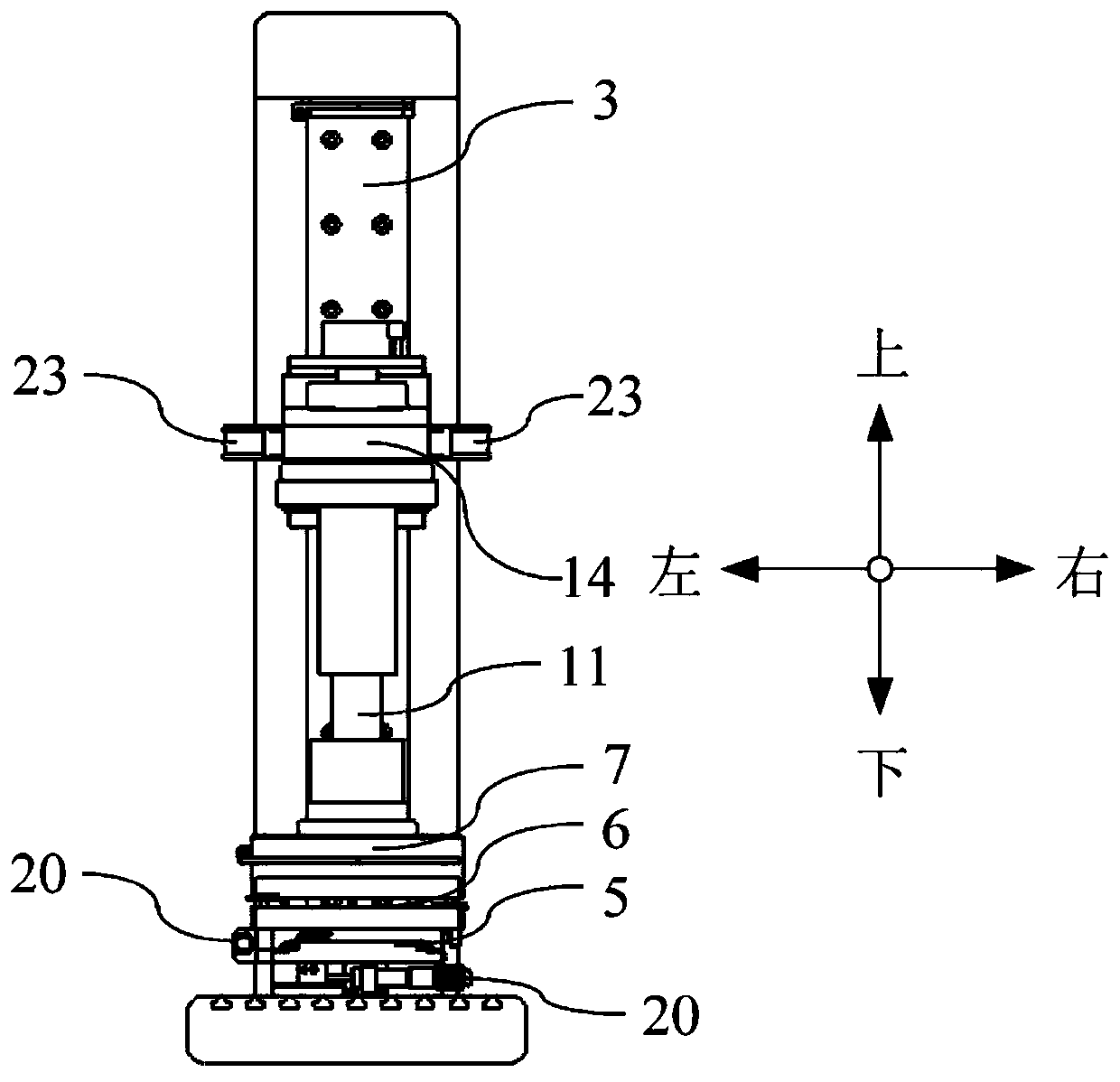
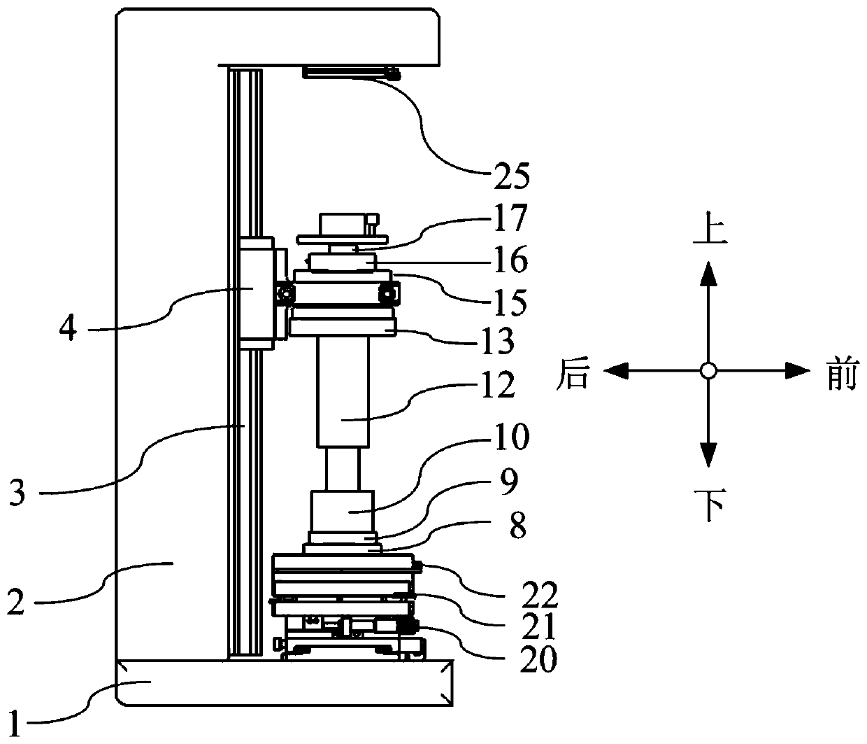
[0074] A rapid preparation device for rock direct tensile samples, such as Figure 1-10 As shown, it includes a base 1 and an inverted L-shaped bracket 2, the base 1 and the inverted L-shaped bracket 2 form a basic frame, and the inside of the basic frame is vertically provided with a slide rail 3, and the slide rail 3 is provided with a sliding block that matches it 4. The slider 4 is connected with a rotary pull-down mechanism through the first connecting piece 14, and a steel sleeve 12 is arranged under the rotary pull-down mechanism, and the rock rod 11 can be rotated into the steel pipe 10 filled with an appropriate amount of cement through the rotary pull-down mechanism , the other end of the steel pipe 10 has been blocked with a plastic buckle cover 9 to prevent the glue from flowing out;
[0075] A horizontal adjustment platform 5, an inclination adjustment platform 6, and an electromagnetic chuck A7 are successively installed on the base 1, and a steel sleeve 8 is ads...
Embodiment 2
[0077] A rapid preparation device for rock direct tensile samples, the structure is as shown in Example 1, the difference is that the rotary pull-down mechanism includes a bearing seat 15, a bearing 16, a rotating shaft 17 and a pull-down handle 23, such as Figure 9-10 As shown, the bearing seat 15 is connected to the slider 4 through the first connection 14 and can follow the slider 4 to move up and down along the slide rail 3. Specifically, the first connection 14 includes a vertical connecting plate and a horizontal connecting plate, The vertical connecting plate is fixed on the side of the slider 4 by bolts, and the bearing seat 15 is fixed by bolts on the horizontal connecting plate. A through hole is arranged in the middle of the horizontal connecting plate. The bearing 16 is installed on the bearing seat 15, and the rotating shaft 17 passes through the through hole and the bearing 16. Inner ring fixed connection;
[0078] A rotating disk 18 is fixed above the rotating ...
Embodiment 3
[0082] A rapid preparation device for direct tensile samples of rocks, the structure is as shown in Example 1, the difference is that the steel sleeve 8 plays the role of placing the combination of the plastic buckle cover 9 and the steel pipe 10, wherein the steel sleeve 8 and the plastic buckle The profile of cover 9 is substantially similar, and the shape is as Figure 4 , 5 As shown, the steel sleeve 10 need not be too high, the inner diameter of the steel sleeve 10 matches the outer diameter size of the plastic buckle cover 9, and the inner diameter of the plastic buckle cover 9 matches the outer diameter size of the steel pipe 10; A proper amount of liquid cement will be injected into the steel pipe 10 in advance, and the lower end must be blocked with a plastic buckle cover 9. The purpose is to bond the rock rod 11 in the steel pipe 10 sealed with the plastic buckle cover 9, which can save economic costs. Because steel pipe 10 can be cut by standard steel pipe (section...
PUM
| Property | Measurement | Unit |
|---|---|---|
| Thickness | aaaaa | aaaaa |
| Diameter | aaaaa | aaaaa |
| Adsorption | aaaaa | aaaaa |
Abstract
Description
Claims
Application Information
 - R&D
- Intellectual Property
- Life Sciences
- Materials
- Tech Scout
- Unparalleled Data Quality
- Higher Quality Content
- 60% Fewer Hallucinations
Browse by: Latest US Patents, China's latest patents, Technical Efficacy Thesaurus, Application Domain, Technology Topic, Popular Technical Reports.
© 2025 PatSnap. All rights reserved.Legal|Privacy policy|Modern Slavery Act Transparency Statement|Sitemap|About US| Contact US: help@patsnap.com


