
Hydraulically driven differential motion rotary breast interventional robot under MRI

A differential motion and rotary technology, applied in the field of medical equipment, can solve problems such as large error, large process energy loss, and complex transmission

Inactive Publication Date: 2019-10-22
HARBIN UNIV OF SCI & TECH
View PDF14 Cites 3 Cited by
  • Summary
  • Abstract
  • Description
  • Claims
  • Application Information

AI Technical Summary

Problems solved by technology

However, in the process of completing the interventional operation, the movement of the upper movable bracket of the horizontal guide rail on the guide rail is converted into the rotation of the cylinder in the vertical plane with the lower guide rail as the base point. This process has a large amount of motion loss, resulting in low motion accuracy. big error
[0008] Application publication number CN104825231A discloses a magnetic resonance-guided breast cancer minimally invasive interventional surgery robot and its control method. In this invention, the first driving mechanism drives the first transmission mechanism, thereby driving the first screw to rotate, and then driving the first The mobile platform moves along the Z-axis direction, the transmission of this process is complex and difficult to control
[0009] Application publication number US6889073B2 discloses a breast biopsy and treatment system in an MRI environment. The MRI biopsy device includes radio frequency receiving coils for imaging bilateral breasts. The coils are opened at the front and side to provide access to the breasts when the patient is in the scanner. At the same time, the support column of the device is installed on a rotatable gear, and the rotatable gear is driven to rotate by the second gear, and the second gear rotates through the transmission shaft. The transmission process is complicated and the process energy loss is large.

Method used


Image

  • Hydraulically driven differential motion rotary breast interventional robot under MRI
  • Hydraulically driven differential motion rotary breast interventional robot under MRI
  • Hydraulically driven differential motion rotary breast interventional robot under MRI

Examples


Embodiment Construction

[0042] In order to make the object, technical solution and advantages of the present invention clearer, the present invention is described below through specific embodiments shown in the accompanying drawings. It should be understood, however, that these descriptions are exemplary only and are not intended to limit the scope of the present invention. Also, in the following description, descriptions of well-known structures and techniques are omitted to avoid unnecessarily obscuring the concept of the present invention.

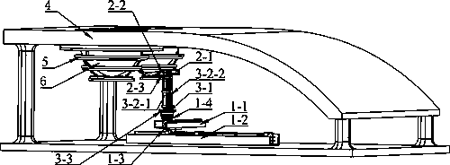
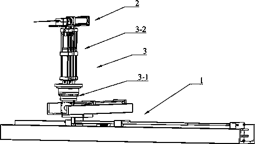
[0043] Such as figure 1 , figure 2 , image 3 , Figure 4 , Figure 5 , Image 6 , Figure 7 , Figure 8 , Figure 9 , Figure 10 , Figure 11 , Figure 12 , Figure 13 , Figure 14 As shown, the specific embodiment of the present invention adopts the following technical solutions, which include a positioning module 1, an X-axis hydraulic cylinder 1-1, an X-axis hydraulic cylinder cylinder block 1-1-1, an X-axis hydraulic cylinder rod body 1-1-2,...


PUM


Abstract

The invention discloses a hydraulically driven differential motion rotary breast interventional robot under MRI, and belongs to the field of medical instruments. The robot is composed of a positioningmodule, a puncture module, a rotary module and a breast tissue fixing module. The positioning module can adjust the position of a biopsy mechanism, the puncture module can achieve the puncture of thebreast tissue, the rotary module can make the puncture module rotate by 360 degrees around the breast tissue and can adjust the pitch angle of a biopsy gun, and the breast tissue fixing module can stabilize the breast tissue. The robot can help a doctor complete a breast interventional operation in a nuclear magnetic instrument with limited space, reduce the work intensity of the doctor, improvethe operation precision and increase the success rate of the operation.

Description

technical field [0001] The invention discloses a hydraulically driven differential motion rotary mammary gland interventional robot for MRI, relates to the field of medical equipment, and is particularly applied to breast interventional surgery in a nuclear magnetic environment. Background technique [0002] At present, breast interventional surgery is generally performed manually by doctors. The whole process is time-consuming and labor-intensive. Doctors are highly fatigued and patients feel pain. Breast interventional robots can help doctors complete surgery. The robot has the advantages of high positioning accuracy, and will not affect the accuracy of surgery due to patient body movements or doctor's hand shaking, and MRI has good resolution of soft tissues. [0003] Application publication number CN 103876786 A discloses a breast interventional robot compatible with nuclear magnetic resonance. The positioning module is mainly driven by a screw nut, and the motor is plac...

Claims


Application Information

Patent Timeline
Patent Type & Authority Applications(China)
IPC IPC(8): A61B17/34A61B34/30A61B10/02A61B90/17A61B34/20
CPCA61B17/3403A61B34/30A61B10/0275A61B90/17A61B34/20A61B2017/3405A61B2017/3409A61B2034/2065
Inventor 张永德孙立一梁德县黄致远刘琪峰秦培旺
Owner HARBIN UNIV OF SCI & TECH
Learn More