Control device-built-in cylinder servo motor
a technology of cylinder servo motor and control device, which is applied in the direction of program control, electric controller, instruments, etc., can solve the problems of reducing positioning accuracy, not taking into account, and degrading positional accuracy
- Summary
- Abstract
- Description
- Claims
- Application Information
AI Technical Summary
Benefits of technology
Problems solved by technology
Method used
Image
Examples
first embodiment
[0050]A first embodiment of the present invention will be described below with reference to FIGS. 1 to 14.
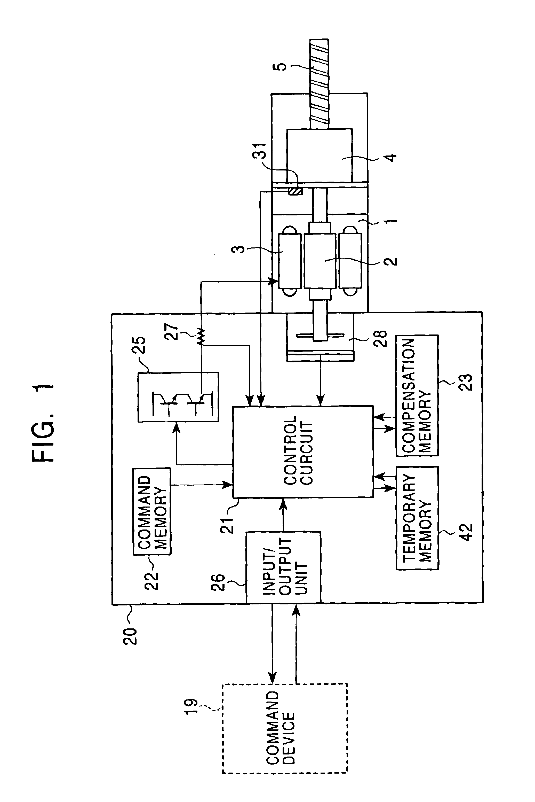
[0051]FIG. 1 is a structure diagram of a cylinder servo motor according to the first embodiment. This figure shows the structure of the cylinder servo motor in a normal operation mode.
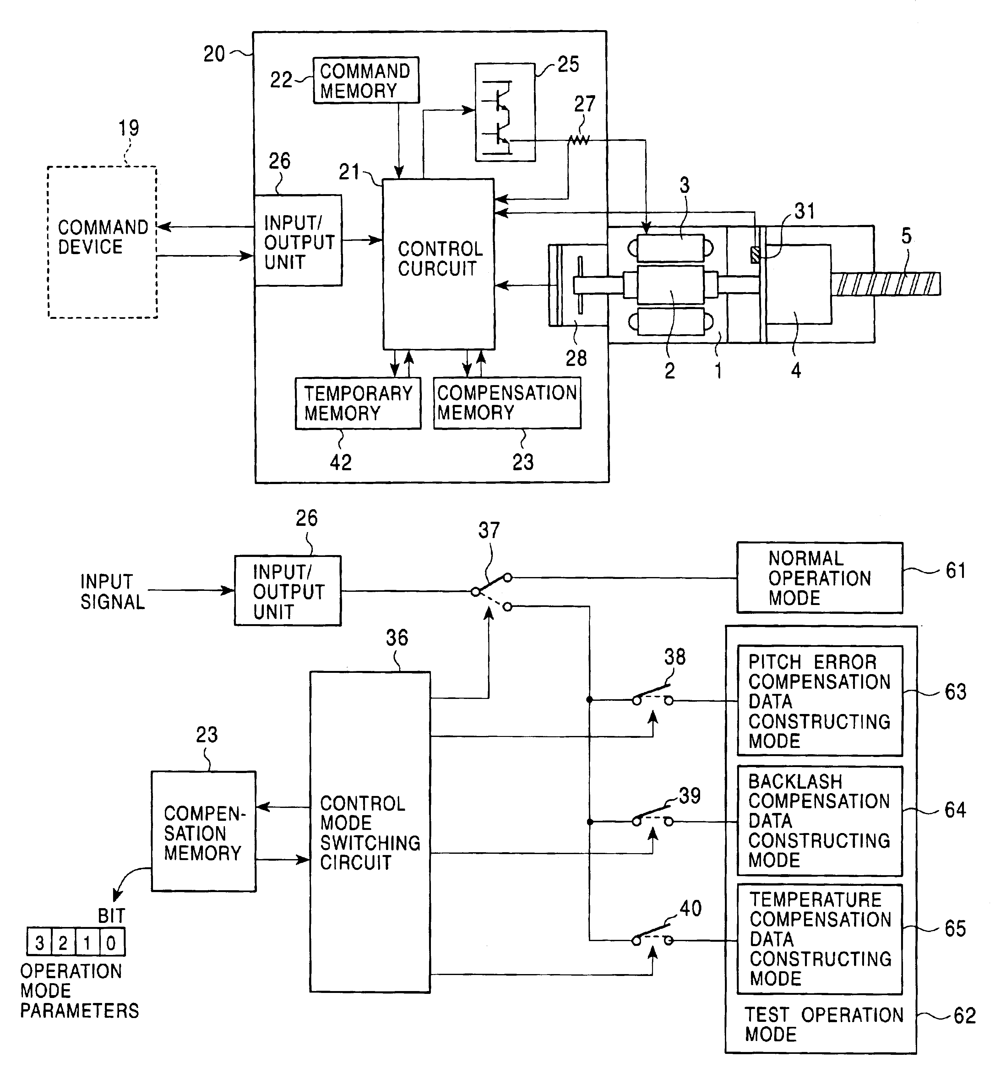
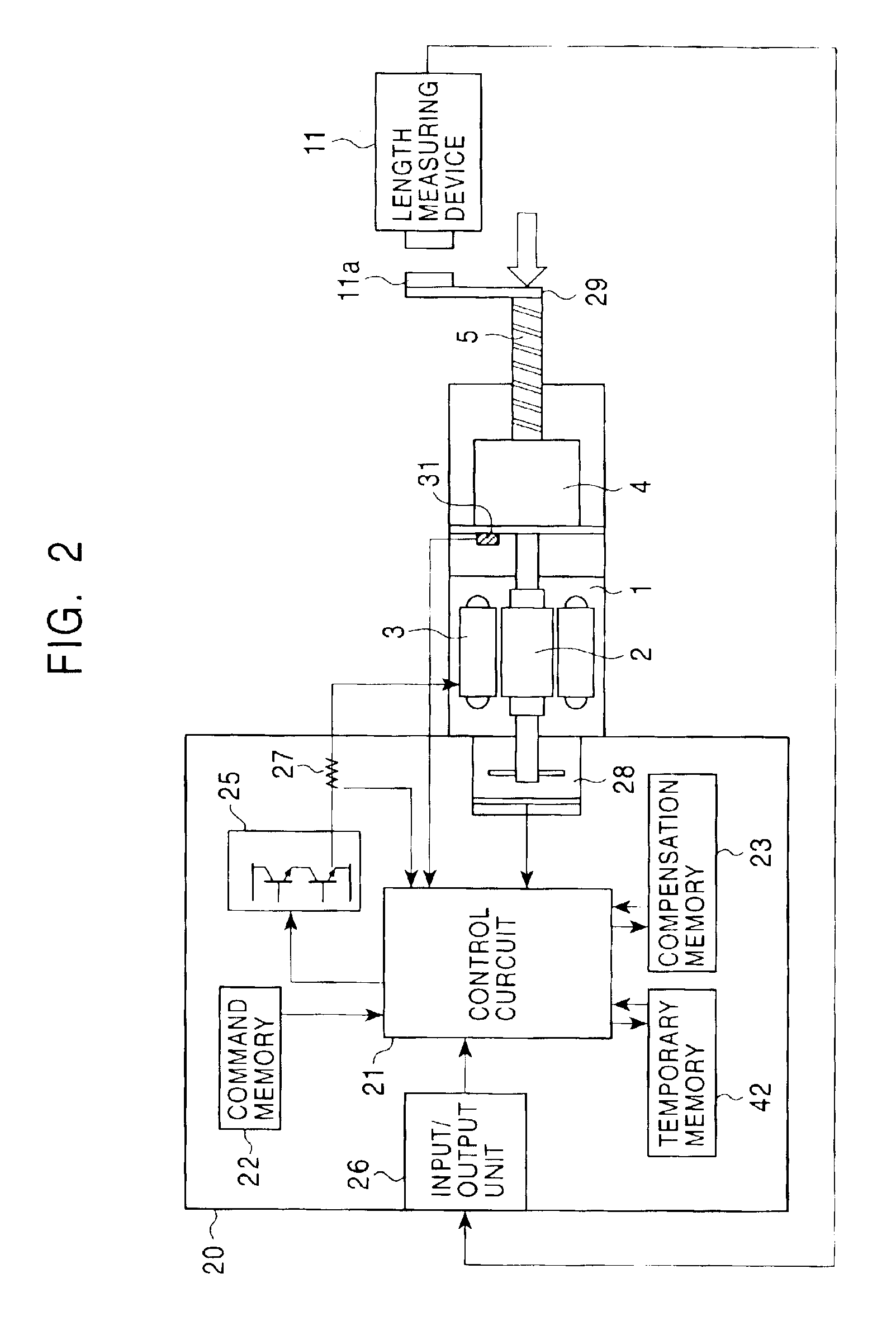
[0052]With reference to the figure, reference numeral 1 denotes a servo motor unit, which is constructed of a rotor 2 and a stator 3; 4, a ball nut which is connected to the rotor 2 at the side at which a load is applied; 5, a ball screw which is screwed into the ball nut 4 and which serves as an output shaft that moves in the axial direction thereof. A rotational / linear motion converting mechanism is formed by the ball nut 4 and the ball screw 5. In addition, reference numeral 20 denotes a control unit; 21, a control circuit which is constructed of a built-in microcomputer, etc., and which servo controls the servo motor unit 1; 22, a command memory which is used in a test operation mode, which wil...
third embodiment
[0134]Without using the method described above in the second embodiment, the correction factors may also be simply calculated as: a=ɛ+ɛ′2,b={L0-(x0+ɛ0+f(x0+ɛ0-a))}+{L1-(x1+ɛ1+f(x1+ɛ1-a))}2(14)
Alternatively, they may also be calculated as: a=0,b=L·ɛ+ɛ′2(15)
Equation (14) is used in the case in which the positional relationship between the detector and the output shaft has changed due to disassembling, etc., of the cylinder servo motor. The positional relationship changes at a time when, for example, the rotational / linear motion converting mechanism is disassembled and mounting angles of the rotor, nut and output shaft are changed. This calculation corresponds to FIG. 23, in which the error curve e=f(x) is corrected by moving it in parallel in the horizontal direction. Equation (15) is used in the case in which the length of the ball screw is changed due to abrasion, etc., and the errors at the stroke end positions are used for calculating an offset. This calculation corresponds to F...
fourth embodiment
[0135]In the above-described second and third embodiments, the correction factors used for compensating the detection angle in the process of obtaining the pitch error (that is, the compensation data for the pitch error), which is stored in the positioning error table in advance in association with the detection angle, are calculated. Then, the pitch error corresponding to the compensated detection angle, which is calculated based on the correction factors, is obtained from the compensation memory 23 and used for compensating for the pitch error. More specifically, even when errors due to age deterioration, disassembling for repair, etc., have occurred, they can be compensated for without correcting the pitch error data itself, which is stored in the compensation memory 23 in association with the detection angle. However, the above-described errors may also be compensated for without correcting the detection angle detected by the rotation detector 28, by correcting the pitch error d...
PUM
 Abstract
Description
Claims
Application Information
 - R&D
- Intellectual Property
- Life Sciences
- Materials
- Tech Scout
- Unparalleled Data Quality
- Higher Quality Content
- 60% Fewer Hallucinations
Browse by: Latest US Patents, China's latest patents, Technical Efficacy Thesaurus, Application Domain, Technology Topic, Popular Technical Reports.
© 2025 PatSnap. All rights reserved.Legal|Privacy policy|Modern Slavery Act Transparency Statement|Sitemap|About US| Contact US: help@patsnap.com


